Working with Panels
Much of the functionality in HyperMesh is centered around the use of panels. While there are often many ways to get to a function within HyperMesh, most often the actions lead the user to the panel area to select entities, enter values and execute functions. The panel area is split into seven pages and on each page are panels that allow the user to utilize all of the functionality in HyperMesh. Even if the user accesses a function through the use of the menu bar or the toolbars, much of the information will be entered in the panel area. While this manual cannot explain the functionality of every panel, much of the panel functionality is common amongst all of the panels and thus learning one panel will assist the user in the use of all panels.
This section introduces you to common panel attributes and controls.
To learn more about the panels, select one of the topics below.
In HyperMesh, panels have three general layouts; the Basic Panel, Panel with Sub Panels and Panels with Sub Panels organized in Columns. Their look and functionality will be described below.
The Basic Panel

Translate Panel
Panel with Traditional Sub-Panels

Node Edit Panel
Panel with Image Sub-Panels

Nodes Panel
Panel with Sub-Panel and Columns

Surface Edit/trim with nodes
Actions in HyperMesh usually require you to first navigate to the functionality, then select the entities to work on – unlike in some other software, where you first select entities, and then say what to do with them. Generally panels are used in a Left to Right manner and those with columns are used in a left to right and top to bottom manner using the following steps:
Step 1: “What to Do”
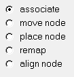
This step only applies to panels with Sub Panels. The user picks the functionality within the panel that is desired by picking the appropriate Sub Panel radio button. The example below is from the Node Edit panel and the “associate” sub functionality is chosen.
Step 2: “Method to Use”
This step only applies to Panels with Sub Panels that are organized in columns. Often, Sub Panels are organized into different columns when there are more than 7 Sub Panel options. The column organization groups like functionality together in instances where the entire panel is not needed for information entry. In this case the user picks the Sub Panel in Step 1 and then chooses the method they wish to use within that sub panel and follows the column top to bottom. The example below shows the Surface Edit panel with the trim with surfs/plane sub functionality chosen. You can see the three columns providing access to either the “with plane”, “with surfs” or “self intersecting surfs” options.

Step 3: “What to do it to”
After selecting the method to use, the user will select the entities they wish to perform the function on. The entity selection is shown below, it is nearly always a yellow button that is used to select entities to work with or on.
![]()
Step 4: “How to do it”
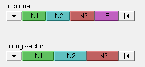
After selecting the entities, the user defines parameters that dictate how the function will be performed.
Step 5: “Do the action
Clicking the green “action” button performs the desired function while the “reject” button will reject the last performed function.

Within the panels there are many buttons and options that will be explained below:
Switches - ![]()
These allow the choice of multiple options through a pop up menu
Toggles - ![]()
The toggle will change the function between 2 options.
Reset - ![]()
This will reset the selection of any entities.
Extended Entity Selection - ![]()
Clicking the yellow selection button will open the extended selection window. This provides numerous tools allowing for the advanced selection of entities. See the Selection Methods section for more information.
Direction/Plane Selection -
X, Y, Z Axis - ![]()
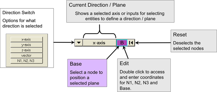
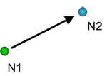
N1, N2 and N3 - ![]()
Select 2 Nodes (N1 & N2) – This defines a directions from N1 to N2 where a vector type direction is required. When a plane is required the plane is defined as that which is normal to the vector N1 to N2 and its location at the B node.
Select 3 Nodes (N1, N2 and N3) – This defines a plane whose normal defines a direction when a vector direction is required. Positive of the normal is defined by the “Right Hand Rule.” In the event a plane is required the plane is that which is created by the three nodes with its location at the B node.
