Shell Meshing using Automesh
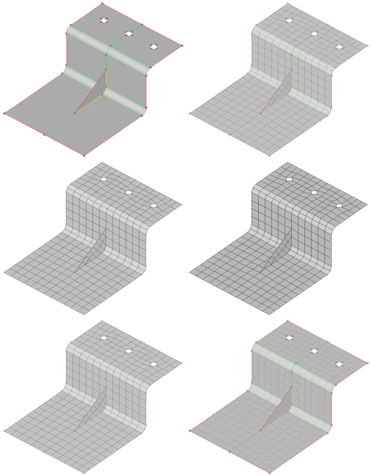
The optimal starting point for creating a shell mesh for a part is to have surface geometry defining the part. The most efficient method for creating a mesh representing the part includes using the Automesh panel and creating a mesh directly on the part’s surfaces.
The Automesh panel is a key meshing tool in HyperMesh. Its meshing module allows you to specify and control element size, density, type, and node spacing, and also perform quality checks before accepting the final mesh.
A part can be meshed all at once or in portions. To mesh a part all at once, it may be advantageous to first perform geometry cleanup of the surfaces, which can be done in HyperMesh.
The purpose for this section is to help you become proficient with using the Automesh panel’s meshing module. In this section, you will learn how to:
- Mesh all the surfaces at once specifying different element sizes and element types.
- Practice changing the element density along surface edges.
- Practice checking element quality and changing the mesh pattern by changing the mesh algorithm.
- Preview the mesh on all the unmeshed surfaces.
- Practice changing the element type and node spacing (biasing) along surface edges.
- Re-mesh surfaces.
To learn more about the panels, select one of the topics below.
The Automesh function in HyperMesh allows for the rapid generation of a quality mesh on one or multiple surfaces. Within the automesh panel there are many options available which provide the user a high level of control over the final mesh.

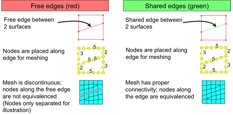
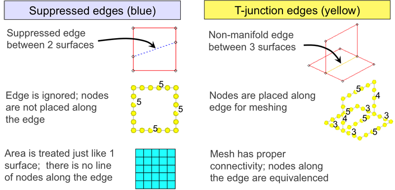
Automeshing of surfaces is dependent on surface topology, which is the connection of adjacent surfaces edges. Properly connected edges ensure a properly connected mesh. As discussed, in greater detail, in the previous chapter, topology is represented graphically though edge color.

To properly represent a part with shell elements, those elements must be properly connected. Unconnected elements are in effect a slice in a part and all stresses, strains and deformations will stop at the unconnected region.
HyperMesh maintains edges in a part. This means that if you see a surface edge in the mesh (unless it is suppressed) you will see that same edge in the mesh. HyperMesh will place nodes along that edge and if the edge is properly connected then there will only be one set of nodes that will be shared by elements on either side of the edge. Node sharing between multiple elements is how elements are connected to each other.
Below are examples of how edge topology affects the resultant mesh. There is an example for each of the 4 topological states (colors).


The automesh panel allows meshes to be created and existing meshes to be re-created interactively or automatically on surfaces or existing elements. In this chapter the size and bias subpanel will be the focus. Click the panel below to get started. Choose whether to select elements or surfaces and mouse over the different options of the size and bias subpanel and the other subpanels for a brief description of each. Click return to select elements or surfaces again.
Within the automesh panel are numerous controls to allow for the creation of a quality mesh to individual specifications.
Size and bias Subpanel
This subpanel is the most widely used and is the default for automeshing. Within this panel the user sets the desired element size and type, chooses options for flowing and mapping and then is provided with a preview mesh. From within the meshing module there are many options for mesh refinement. Click on the different subpanels and mouse over the options to see a brief description of each. More information is also available below.
Density
- Adjust – Left clicking on an edge will raise the element density on that edge by one, right clicking will lower the density by one.
- Calculate – Here the user can enter a new element size and either click on an edge to recalculate the density on that edge or click recalc all and change the element size for all the surfaces currently being meshed.
- Set – This option allows for the setting of element densities on a single or all edges to a user set number.
Mesh Style
Use the Mesh Style subpanel to specify the meshing algorithm to use for each face of each domain when you are following a surface-based approach. The shape of the icon on each face identifies the algorithm that has been specified for that face. This subpanel lets you change the mesh style (quads, trias, mixed) for individual, specific surfaces.
- Toggle a surface to cycle through element types: tria, quad, mixed, right-tria, or quad-only.
- Toggle a surface to cycle through mesh mapping methods: autodecide, rectangle, triangle, pentagon, circle, free (unmapped).
- Set a surface, or all surfaces, to use any combination of options: align flow, size control, skew control, or automatic smoothing.

This panel also allows the user to define the method or style of meshing. The “style” is the manner in which the mesh transitions between different density values.
- Autodecide - Automatically selects one of the other methods.
- map as rectangle - Used for rectangular shaped areas (can sometimes be used for others as well).
- map as triangle - Used for triangular shaped areas.
- map as pentagon - Used for pentagonal shaped areas.
- free (unmapped) - Used for anreas of any shape.
Biasing
The biasing subpanel allows the user to control the distribution of nodes during the nodes seeding by selecting biasing in the form of linear, exponential or bell curve distributions.
