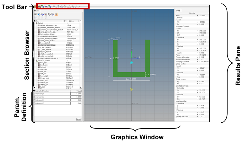
The HyperBeam toolbar contains the following option buttons:

The first option is a simple background grid on/off control. This is represented by the grid line icon, and allows you to quickly resolve the relative size of each section.
The second set of options, which are represented by the four differently oriented channel section icons, allows you to control the orientation with respect to the local origin of a standard section in the HyperBeam standard section library. Standard sections within the solver libraries already have a set orientation that maps to the solver, so this option is not available for any sections other than those defined in the HyperBeam library.
The third set of options is the view controls (zoom, fit, and pan). All these options are available through CTRL + mouse and follow HyperMesh mouse controls. The icons are as follows, from left to right:
- Fit to window
- Zoom in / Zoom out: This is controlled by left- and right- clicking the icon.
- Fit to circle: This works just like HyperMesh's circle zoom.
- Move center: This is a panning tool that allows you to simply grab the screen and move it.
The fourth set of options consists of section editing and sketching tools. These allow you to create and edit shell and solid sections as well as modify section parameters. The icons are as follows, from left to right:
- Create shell part or solid perimeter: This is the primary tool used to sketch shell and solid sections and is activated automatically when defining a new shell or solid section canvas.
- Joint parts/Split part at vertex: To join two parts that meet at a common point end, left-click on the first part, then left-click on the second part to merge it into the first part.
To split a part at a vertex, left-click on the part that you wish to split, then right-click on the vertex that you wish to split the part at. The part splits into two parts.
- Move vertex / Edit dimension / Edit thickness: This tool is active for standard, shell and solid sections and has 3 distinct functions. For standard sections, this tool allows you to edit any of the parameters displayed on the section. For shell sections, this tool allows you to quickly snap any vertex to the predefined grid. For solid sections, this tool allows you to quickly snap any vertex to the predefined grid.
- Add vertex / Delete vertex: In this mode, left clicking on or near any part (for a shell) or perimeter (for a solid) will create a new vertex on the nearest part or perimeter. The part or perimeter will be diverted to now run through the new vertex. If a clicked point is nearer to the end of a part than a segment of it, the part will be extended.
- Delete shell part or solid perimeter. In this mode, left clicking on or near any part (for a shell) or perimeter (for a solid) will delete the nearest part or perimeter.
The fifth set of tools are the Undo/Redo Tools. These tools allow you to do the following functions, listed in order from left to righ; Undo all changes, Undo last change, Redo last change, and Redo all changes.
The sixth set of tools are the measuring tools:
- Find moments at mouse location: Selecting this icon activates an interactive mode. When you click on a point in the graphics area, the Local moments of inertia dialog appears. From this dialog you can review the following information; The Y and Z coordinates of the point selected, The Y and Z offsets from the shear center and centroid and The moments of inertia Iyy, Izz, and Iyz for the section relative to the selected point.
- Measure section with ruler: Selecting this icon activates an interactive mode. When you click two or more points in the graphics area, lines are created similar to the way a shell section is created. If two points are selected, the dy and dz distances between the points are displayed, as well as the total length of the line. If three or more points are selected, the total length of the line is displayed. Right-clicking removes the previously selected point.
The last set of icons are tools for taking screen shots of various components in HyperBeam. The icons are as follows, from left to right:
- Save image to file/clipboard
- Capture full image
- Capture graphics area
- Capture results area
- Capture rectangular area
- Save graphics to jpg


