Connector Tools
There are a couple of different ways connectors can be created in HyperMesh. This section will look at creating connectors strictly through the panels as well as the Connector Browser. Finally we will also look at the visualation tools available.
Expand the sections below to learn more about connector tools.
Within the Connectors panel, there are several other panels available for creating and editing connectors. Below is an image of the available panels within the Connectors panel as well as a short description of each panel.

-
spot – Use the connector Spot panel to create connectors that represent point connectors such as spot welds. These connectors can be realized as standard or custom weld representations.
-
bolt – Use the connector Bolt panel to create connectors which will be represented as a 1D element construct. There are three base methods to determine the nodes to be connected: hole detection, cylinder definition, and a combination of both.
-
seam – Use the connector Seam panel to create connectors that represent line connectors such as seam welds. These connectors can later be realized as standard or custom weld representations.
-
area – Use the connector Area panel to create connectors that represent connections of larger regions, such as adhesives. These connectors can later be realized as standard or custom weld representations.
apply mass – adds a mass value to entities
Used to represent mass of parts that are not present in the model
fe absorb – Create new connectors from existing elements of recognizable FE representations of welds, bolts, adhesives, etc.
add links – Add link entities to existing connectors
unrealize – Delete FE representations of welds / bolts / adhesives associated with existing connectors
-
compare – Checks the Master Connection File against the displayed model file
quality – Check for duplicate connectors, combines connectors, and checks the quality of realized elements
The Connector Browser is a hierarchal browser that provides information about connectors as well as the ability to edit connectors. The browser includes two major areas:
The Link Entity Browser in the top of the tab, which displays information for the linked entities in the model, and
A tree view of all the connections contained in the model, located in the lower half of the tab. These connectors display in folders, organized based on the respective realization types. The names of the folders are obtained from the FE configuration names specified for respective solvers in the feconfig.cfg file.
The Connector Browser can directly affect what is displayed in the graphics area by selecting, highlighting, showing or hiding entities. It also provides quick access to HyperMesh functionality such as finding links, finding connectors from links or realizations, renumbering, masking, creating and deleting; and quick access to connector entity functionality such as adding links, removing links, updating links, and editing connector attributes. The Connector Browser and the HyperMesh database synchronize to ensure that all changes to the connector or component information in the database is reflected correctly in the browser at all times.
The Connector Browser can be configured to display only the information that you wish to see; the current configuration is saved, so that the next time you open the browser it opens with the same configuration as the last time that it was used.
The Connector Browser can be accessed by selecting View > Browsers > HyperMesh > Connectors.
Use the interactive video below to learn more about the Connector Browser.
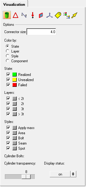
The Visualization controls allow you to change many of the visual states in HyperMesh and HyperView. This is accessed from the ![]() icon in the Display toolbar. To access the connector tools, select the connector icon
icon in the Display toolbar. To access the connector tools, select the connector icon ![]() . This allows you to:
. This allows you to:
Color connectors by state, layers, or component
Visibility by state or layers (can turn the display on or off)
Control size of connector display
