Setting Up Loading Conditions
A finite element solver can solve for responses of parts to loading conditions placed on them. The loads can be in the form of any combination of boundary constraints, forces, pressures, temperatures, etc. This section focuses on defining the loading conditions on a model.
In this section, you will learn how to:
- Create constraints (OptiStruct SPC) on the channel's geometry lines
- Create a force (OptiStruct FORCE) on the bracket to simulate a pressing load on it
- Define a load step (OptiStruct SUBCASE)
Analysis Setup
Analysis setup is the definition of all information for an analysis besides the mesh including:
- Specification of the solver to be used
- Creation of materials, properties, etc.
- Assignment of a solver specific format to HyperMesh entities
- Creation of boundary conditions (constraints, loads, contacts, etc.)
- Creation of loadcases from a combination of boundary conditions
- Definition of other required information (solution requests, general run parameters, etc.)
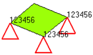 |
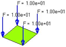 |
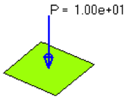 |
|---|---|---|
| Constraints | Forces | Pressures |
This section will focus on the creation of boundary conditions
Supported Entities
FE Loading
- Loads (constraint, force, pressure, moment, temperature, flux, velocity, acceleration)
- Equations (mathematical link between nodes)
- Contacts
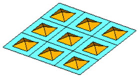
Contacts
- Group (defines contact between entities)
- Contact Surfs (defines a list of entities that can be used as master or slave in a group)
Reference Entities
- Sets (a simple list of a particular type of entity)
- Blocks (a list of entities contained within a box shape)
Coordinate Entities
- Systems (coordinate axes)
- Vectors
Plotting
- Curves (X-Y data)
- Plots (a display of curves with axes)
Output Requests
- Loadsteps (combinations of load collectors)
- Output Blocks (request output from an analysis for certain entities)
- Control cards (job-level, global parameters for the analysis)
Loads on Geometry
HyperMesh allows the user to place loads on geometry before the mesh is ever created. Then using the BCs>Loads on Geometry pull down, those loads will be mapped to the elements that were created from that geometry. This is a time saving advantage as the user only needs to pick one, or at most a few, geometric entities to ultimately create hundreds or even thousands of loads or constraints.
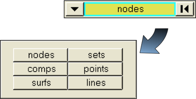
To use this, change the entity selector from a node or element selection to a geometric selection such as surfs or lines.
Then after the part is meshed, using the Loads on Geometry function, the loads will be automatically mapped to elements created from that geometry.