Refine Mesh by Pattern
Create a regular orthogonal mesh.
Before you begin, make sure the initial mesh is a regular mapped quad mesh, and not a free quad mesh.
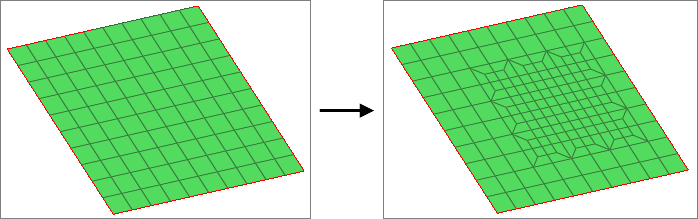
Figure 1. Pattern Based Mesh Refinement
-
Use the Select node: Nodes selector to select the center node to start the
uniform mesh refinement.
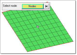
Figure 2. -
Define the Refinement box, which determines the constant refinement zone.
Elements inside this box should be the same size.
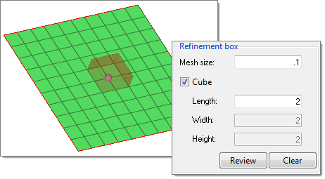
Figure 3. -
Define the Transition box.
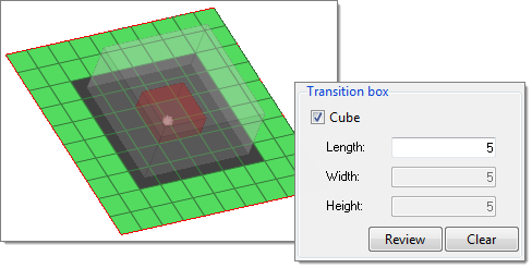
-
Click Mesh.
Attached 1D elements are refined.
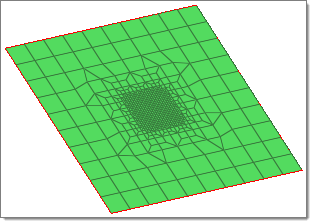
Figure 4.