EM Lattice Meshing
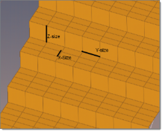
EM Lattice meshing is a method to create an axis-parallel mesh for 2D and 1D geometry input.
Create EM Lattice Mesh
The Lattice mesh is created within the specified bounding box.
View new features for Engineering Solutions 2020.1.
HyperWorks Engineering Solutions is a modeling and visualization environment for NVH, Crash, CFD, Drop Test and Aerospace using best-in-class solver technology.
Discover Engineering Solutions functionality with interactive tutorials.
Noise, Vibration and Harshness (NVH) is an important vehicle attribute that directly affects the customer experience.
The Crash application offers a tailored environment in HyperWorks that efficiently steers the Crash CAE specialist in CAE model building, starting from CAD geometry and finishing with a runnable solver deck in Radioss, LS-DYNA and PAM-CRASH 2G.
HyperWorks offers high quality tools for CFD applications enabling the engineer to perform modeling, optimization and post-processing tasks efficiently.
The Drop Test Manager is an automated solution that allows you to either simulate a single drop test or a choice of multiple iterations with the aim of finding the sensitivity of process variables like initial orientation and drop height in a typical drop test by controlling the run parameters and conditions with ease.
Many essential utility tools using HyperWorks-Tcl have been developed over the years to support Aerospace customers. A few tools have been collected and upgraded to be compatible with this release.
Currently supported solver interface versions.
Load a different solver interface in Engineering Solutions.
Engineering Solutions uses three types of external interfacing.
Overview of the Abaqus Interface.
Overview of the ANSYS interface.
Overview of the LS-DYNA interface.
Overview of the Nastran interface.
Overview of the PAM-CRASH 2G interface.
Overview of the OptiStruct interface.
Overview of the Radioss interface.
A solver interface is made up of a template and a FE-input reader.
Support provided by the CAD readers and writers.
Browsers supply a great deal of view-related functionality in Engineering Solutions by listing the parts of a model in a tabular and/or tree-based format, and providing controls inside the table that allow you to alter the display of model parts.
Panels contains pre-processing and post-processing tools.
Create, edit, and cleanup geometry.
Learn about the different types of mesh you can create in HyperWorks.
Elements are FE idealizations for a portion of a physical part.
Smooth Particle Hydrodynamics (SPH), Finite Point Method (FPM) is a technique used to analyze bodies that do not have high cohesive forces among themselves and undergo large deformation, such as liquids and gases.
1D mesh that allows accurate testing of connectors, such as bolts, and similar rod-like or bar-like objects that can be modeled as a simple line for FEA purposes.
A surface mesh or "shell mesh" represents model parts that are relatively two-dimensional, such as sheet metal or a hollow plastic cowl or case.
Supported 2D elements.
Automatic meshing generates a mesh of plate elements according to your specifications using surface geometry or existing shell elements.
Create a midsurface mesh with a thickness from 3D geometry.
Automatically generate a mesh at the midplane location, directly from the input geometry (components, elements, solids or surfaces), without first creating a midsurface.
Assign a thickness to shell elements that represent the middle surface of a solid part.
Shrink wrap meshing is a method to create a simplified mesh of a complex model when high-precision models are not necessary, as is the case for powertrain components during crash analysis.
EM Lattice meshing is a method to create an axis-parallel mesh for 2D and 1D geometry input.
2D BL meshing is a method to create a 2D mesh with or without boundary layers on planar sections defined by sets/groups of edges defining closed loops.
Periodic meshing is a method to create a grid containing rotational and/or translational symmetric boundaries, for example rotating machinery.
Volume mesh or "solid meshing" uses three-dimensional elements to represent fully 3D objects, such as solid parts or sheets of material that have enough thickness and surface variety that solid meshing makes more sense than 2D shell meshing.
Mesh controls are used to automate and streamline the meshing process.
Evaluate the overall quality of a mesh, and resolve criteria violations.
Modify your mesh by detect holes, locating edges or features, refining mesh pattern, and so on.
Create connections between parts of your model.
Create, organize, and manage the CAE parts.
Perform automatic checks on CAD models, and identify potential issues with geometry that may slow down the meshing process using the Verification and Comparison tools.
Overview of how to build a finite element model.
Morph the shape of your finite element model.
Setup an Optimization in Engineering Solutions.
Convert finite element models to another solver format.
Study relationships between data vectors in results files.
Learn how to use post-processing functions.
Learn about the different types of mesh you can create in HyperWorks.
A surface mesh or "shell mesh" represents model parts that are relatively two-dimensional, such as sheet metal or a hollow plastic cowl or case.
EM Lattice meshing is a method to create an axis-parallel mesh for 2D and 1D geometry input.
EM Lattice meshing is a method to create an axis-parallel mesh for 2D and 1D geometry input.

voxelszx * meshextx,voxelszy * meshexty,voxelszz * meshextz
The Lattice mesh is created within the specified bounding box.
(c) 2020. Altair Engineering Inc. All Rights Reserved.