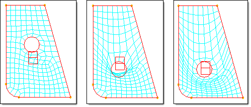
HyperWorksEngineering Solutions is a modeling and visualization environment for NVH, Crash, CFD, Drop Test and Aerospace using best-in-class solver
technology.
The Crash application offers a tailored environment in HyperWorks that efficiently steers the Crash CAE specialist in CAE model building, starting from CAD geometry and finishing with
a runnable solver deck in Radioss, LS-DYNA and PAM-CRASH 2G.
HyperWorks offers high quality tools for CFD applications enabling the engineer to perform modeling, optimization and post-processing
tasks efficiently.
The Drop Test Manager is an automated solution that allows you to either simulate a single drop test or a choice of
multiple iterations with the aim of finding the sensitivity of process variables like initial orientation and drop
height in a typical drop test by controlling the run parameters and conditions with ease.
Many essential utility tools using HyperWorks-Tcl have been developed over the years to support Aerospace customers. A few tools have been collected and upgraded to
be compatible with this release.
Browsers supply a great deal of view-related functionality in Engineering Solutions by listing the parts of a model in a tabular and/or tree-based format, and providing controls inside the table
that allow you to alter the display of model parts.
Perform automatic checks on CAD models, and identify potential issues with geometry that may slow down the meshing
process using the Verification and Comparison tools.
Space frames are models that have a sparse distribution of elements, such as a car body. Space frame models can generally
have element counts in the hundreds of thousands, but their basic structure is rather simple.
Shell models are models that are made up primarily of shell elements, namely, quads, and trias. In general, a shell
model represents many parts, each with numerous features such as holes and edges, and connected together using 1D
elements such as bars and rigids.
Global handles are most effective when used to make general shape changes for a model, such as changing the basic
shape of a model, stretching parts of a model, or making changes that involve the movement of many local handles.
Solid models are models that are made up of solid elements, namely, tetras, pentas, and hexas. In general, a solid
model represents a single part with numerous features such as holes, edges, bosses, flanges and ribs.
Shell models are models that are made up primarily of shell elements, namely, quads, and trias. In general, a shell
model represents many parts, each with numerous features such as holes and edges, and connected together using 1D
elements such as bars and rigids.
Biasing allows you to control the shape of a mesh when applying handle
perturbations.
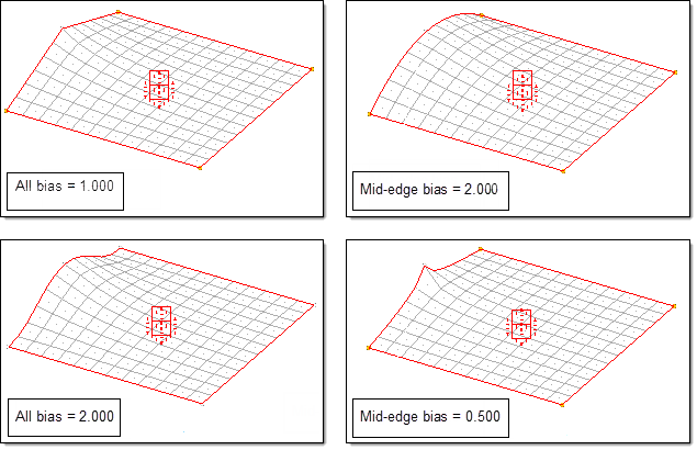
Biasing increases or decreases the influence of a handle over the nodes within its area
of influence. If the biasing values for all of the handles are equal to 1.000, which is
the default value for all handles except for dependent handles on 1D domains, the
morphing between the handles is linear, provided both handles are global handles or they
are located on edge domains. Higher biasing values generate a smooth curvature near the
handles, while lower biasing values generate harsh corners near the handles. To smoothly
change the shape of a domain it is recommended that you use a biasing factor of 1.000 at
the corners, 2.000 at the edges, and 3.000 in the middle.
Biasing can be applied retroactively after a morphing operation. After applying a morph,
you can change the biasing value by selecting the make
retroactive checkbox, and have the current list of applied morphs
updated to reflect the new biasing values. This is useful in selecting a good biasing
value to apply for a given morph. Apply the morphs and change the biasing values
retroactively until you get the shape that you want.