Abaqus
In addition to importing and exporting, HyperMesh allows setting-up analysis conditions required to run a simulation in Abaqus solver. Almost all required analysis conditions such as contacts, constraints, analysis step definition, and output requests can be set-up via the imported Abaqus parts and instances format input files.
Limitations and Restrictions
- You must have a pre-defined Abaqus parts and instances format input file, or a saved HM binary file, with mesh data.
- HyperMesh does not support creating or editing of parts and instances formats within the interface.
- HyperMesh does not support the creation or export of new include files. Include files from the imported input file are preserved and cannot be modified.
- Entities defined in instance level are not supported.
- All the entities should be defined with assembly or model as current in the Part Browser.
- Analysis set-up is restricted to the following:
- Entities such as sets and surfaces cannot be created or edited in a part or instance. The same entities can be created in the assembly level.
- Creation of 1D elements and point masses are allowed in assembly level only.
- Creation of Abaqus connector elements is not yet supported.
- It is highly recommended not to use panels for any set-up except for loads and boundary conditions.
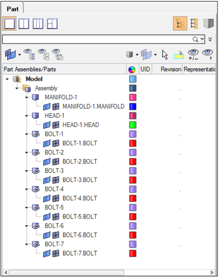
Importing a Parts and Instances Format Input File

Figure 1.
Creating Entities
Entities can be created at the Assembly (before *END ASSEMBLY) or Model level only. While creating entities such as sets, surfaces, kinematic coupling and 1D elements it is required to set the Assembly or model as current in the Part Browser depending upon the position of those entities, and create those entities in a regular way using the Model Browser. Assembly or Model can be set to current by right-clicking on the respective definition and choosing Make Current.
Creating Loads, Boundary Conditions, Contact, and Analysis
All analysis conditions are part of the model level data (after *END ASSEMBLY). The corresponding model is set as current. Loads and boundary conditions can be created through panels with a load collector created for their use in the Model Browser.
The Contact Browser is available to set up the contact/tie between mating parts or components. Tie constraints created using the Contact Browser ensures that the keyword is placed in the assembly level as per solver requirements. The analysis step can be defined using the loadstep manager.
Each of these entities can also be created through the Model Browser and Entity Editor. Similarly, all other entities such as output blocks, group entities such as control cards, model change, contact interference, and so on, can be created with the Model Browser and Entity Editor. They can all be selected for a defined loadstep.
Exporting the Solver File

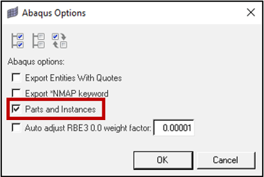
Figure 2.
If the checkbox is unchecked, the solver will write out a flattened Abaqus input file.