ANSYS Section Macro
The Section macro creates and defines section cards for beam and shell sections.
You can create new section, edit existing sections, and use the Engineering Solutions application to create and edit beam section and associate them to section cards.
| Button | Action |
|---|---|
| Help | Provides information about the macro. |
| New... | Opens the Create Section dialog, from which you can specify parameters for a new section and create it. |
| Edit... | Opens the Edit Section dialog, from which you can review and change parameters for an existing material that is selected in the table. |
| Refresh | Refreshes the Engineering Solutions database with changes you made through the Material macro. |
| Delete | Deletes the section card(s) that is selected in the table. |
| Close | Closes the Section macro dialog. |
Right-clicking on a row displays a context menu with the option to delete unused sections. Selecting this option can help you clean up your model by deleting unused sections.
You can also edit sections, edit section properties, and delete sections from the menu that appears when you right-click in the table when a row/section is selected.
Create Section Dialog
Create a new beam, shell or pretension section from the Create Section dialog.
Specify the following options and click Create to create the section card and return to the Section macro, or Create/Edit… to create the section card and open the Card Image panel in Engineering Solutions to specify section properties.
| Option | Description |
|---|---|
| Section Ref No | Type a reference number for the section. If you do not specify a value, a number will be automatically provided that is one higher than the highest current section ID number. |
| Section Name | Type a name for the section. |
| Section Type | Select the type of section to create: Beam, Taper, Shell or Pretension |
| Sub Type | This selection only applies to beam sections. Choose a subtype from the drop-down list. |
| Define by HyperBeam | This option is only available if Beam
Section is selected. Select the check box to
define the section with HyperBeam.
Then select:
When you are in the HyperBeam application, it is possible to create multiple HyperBeam sections. However, only the most recently created section is attached the section card. |
Edit Section Dialog
Use the Edit Section dialog to edit existing beam, shell or pretension sections.
Modify the following options and click Update to save the changes. Click return to return to the Section macro. You can also click Edit Properties… to open the Card Image panel in Engineering Solutions to edit the section’s properties.
| Option | Description |
|---|---|
| Section reference number: | This field is initially populated by the reference number of the section card that you have chosen to edit. You can change the number to any other reference number if the number is not already used by an existing material card. |
| Section name: | This field is initially populated with the current name of the section. You can modify the name of the section. |
| Section type: | You can change the type of section to create. |
| Sub type: | This selection only applies to beam sections. You can select another subtype from the drop-down list. |
| Define by HyperBeam | This option is only available if Beam
Section is selected. Select the checkbox to
modify the section definition with HyperBeam. Then click Edit
HyperBeam… to modify the section in HyperBeam. If you edit a section card that was created with HyperBeam sections, then this checkbox is initially selected. However, you can clear the checkbox and make updates via the card image or vice versa. |
If you make changes to a section, you must click Update to reflect the changes in the card image.
Create a SECDATA Card with the Section Macro
-
From the ANSYS
Utility menu, click
Section....
The Section dialog appears.
-
To create a new section card, click New... at the bottom
of the window.
The Create Section dialog appears.
-
Type a reference number for the section in the Section reference number
field.
A number will already be provided by Engineering Solutions, but you can replace this value.
- Type the name for the section card in the Section name field.
-
Select the type of section you want to create.
- Beam
- Shell
-
If you chose Beam in step 5, then select a Sub type from
the pull-down menu.
Shell sections do not have subtypes.
- At this stage you need to decide if you want to associate a HyperBeam section to the section card image you are creating. If you do not want to use HyperBeam sections, clear the Define by HyperBeam checkbox and skip to step 10.
- To use a HyperBeam section, select Define by HyperBeam.
-
If you have already created sections in HyperBeam
of the selected subtype, you can associate that section with the new section
card image. To create a new section, skip to step
10. Select the existing section option and choose an existing HyperBeam section from the pull-down menu. Skip to step
10.
-
To create a new section in HyperBeam and
associate it to the section card image you are
creating, select the New section option and click
Create to create a section without properties
defined, or Create/Edit... to edit the properties
in the section card before saving.
The HyperBeam application opens.
- Create the section and exit from HyperBeam.
- Click return in the HyperBeam panel in Engineering Solutions to go back to the Create Section dialog. Skip to step 11.
-
To create a new section in HyperBeam and
associate it to the section card image you are
creating, select the New section option and click
Create to create a section without properties
defined, or Create/Edit... to edit the properties
in the section card before saving.
-
Click Create to create a section without properties
defined, or Create/Edit... to edit the properties in the
section card before saving.
The following images indicate the location of the value fields in the SECDATA card, such as W1, W2, t1 and t2.
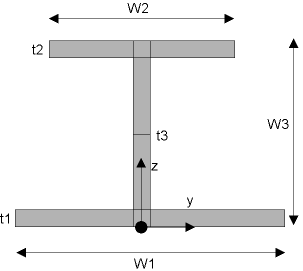
Figure 1. I Beam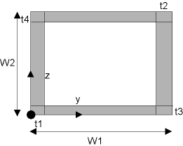
Figure 2. HREC Beam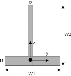
Figure 3. T Beam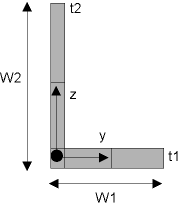
Figure 4. L Beam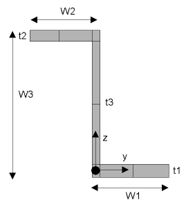
Figure 5. Z Beam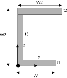
Figure 6. CHAN Beam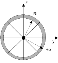
Figure 7. CTUBE Beam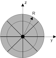
Figure 8. CSOLID Beam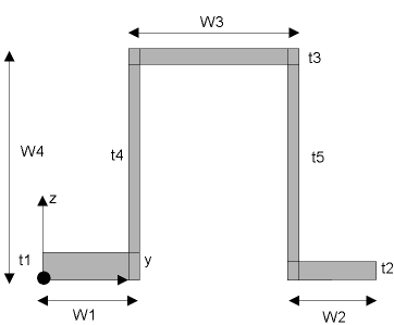
Figure 9. HATS Beam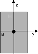
Figure 10. RECT Beam - In the Section dialog, click Close to return to Engineering Solutions.