Modeling Methods
Composite Modeling Methods
Modeling methods for composites include Ply-Based Shell Modeling and Zone-Based Shell Modeling.
Ply-Based Shell Modeling
Ply-Based Modeling
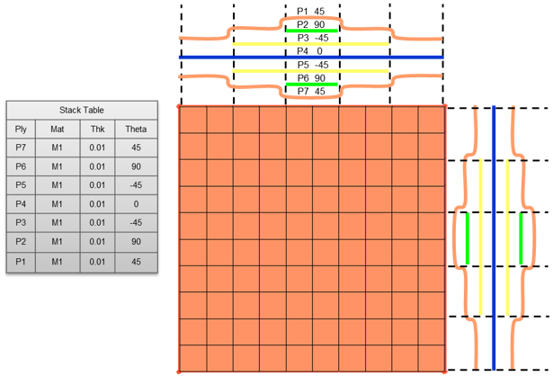
Ply-based modeling provides an FEA methodology which is consistent with the composite manufacturing process. The ply-based modeling entities replace, and can generate, typical solver zone-based composite properties.
- Laminate(s)
- Typically, one laminate per physical part is defined. Primarily, laminates contain the stack of plies. Additionally, laminates specify symmetry and repeats of plies within a laminate, along with information that can manipulate the ABD matrices.
- Plies
- For each laminate, plies define the material, thickness, orientation (from reference on element/property material direction) and shape (Elements, or element sets if FEA-based. Lines, surfaces or solids if geometry-based).
- Template Property
- If user profile is OptiStruct, a PCOMPP is used. If another user profile is selected, a standard zone-based composite shell property is used. The property defines typical solver specific attributes like offset and non-structural mass. Layer information does not need to be entered. It is automatically populated from the defined plies and laminate.

Ply-based models can optionally be used to generate zone-based shell models, continuum shell, and solid models.
Zone-Based Shell Modeling
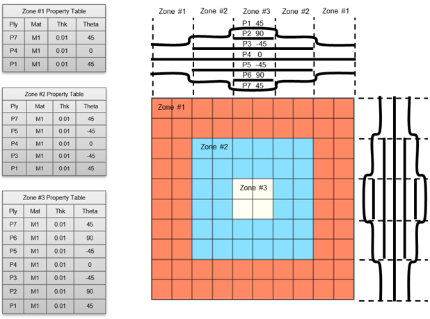
Zone-based modeling.
