Altair HyperWorks 2020 Release Notes
Categories are listed in alphanumeric order.
1D Meshing
New Features
- Beam Modeling (1D Elements)
-

- Rigid/Flexible Connections and MPC Connections
-

2D Meshing
New Features
- Refine
-

Enhancements
- BatchMesher
- Washer treatment for holes in proximity:
- BatchMesher can now create washers for holes in proximity while better honoring the parameter file settings.
- The washer width is adjusted in the proximity area, maintaining the ratio of widths defined in the table. If the priorities of the holes in proximity are different, then for a higher priority hole BatchMesher will try to keep the width defined in the table, and holes with less priority will have an adjusted width within the proximity area.
- For holes in proximity with “auto” treatment defined, BatchMesher tries to reduce the number of layers around the hole.
- Midmesh
- Improvements have been made to the midmesh algorithm to allow extraction
directly at the target element size. This is now the recommended
approach.
- No need to extract at the minimum size and then rebuild to desired target size
- The criteria file is now the primary driver for the extraction process and must be set properly
- Automatically imprint curvature aligned trim lines on cylinders, ensuring good capture of cylindrical structures even with large target element sizes
- Improved fillet capturing, by ensuring minimum size-based seeding
- Facets from Nodes
- This is a new utility to automatically create facets out of node clouds or scanned nodal data sets. For complex curvatures, it also attempts to fix any remaining holes in the model. It is useful for reconstructing faceted models for utilization in CAE simulations.
- Comparison
- Performance improvements for large models of up to 12x, allowing for full assembly comparisons. Ability to get detailed comparisons on a per-component basis.
- Undo/Redo
- All 2D meshing APIs, panels, and HyperWorks workflows are supported for undo/redo.
- Miscellaneous
- Added support for the Nastran method of aspect ratio calculation.
Resolved Issues
- Resolved issues with the "Add Washer" and "Trim Hole" tools, where the collector widget did not have focus upon launching the dialog.
- Added back the missing “Bead recognition” checkbox to the Beads/Bosses tab of the Parameter Editor.
- Fixed an issue with the Parameter Editor where the holes 2D table with the "Elem Mode" column set to "Exact" was not getting written to the parameter file correctly. This was causing the "Elem Mode" to be set as "Minimal" instead.
- Resolved an issue where Acoustic Cavity Mesh did honor the minimum element size and resulted in long execution time.

The HyperWorks Map Thickness tool is fixed to not delete previously created properties, components, or beam sections.
Abaqus Interface
New Features
- Bolt Pretension Manager for Abaqus Interface
- Introducing a new bolt pretension manager tool for Abaqus interface. The tool supports creation of pretension loads/displacements on 1D and 3D bolts.
- Contact Grouping for Abaqus in Contact Browser
- New contact group entity introduced in contact browser that allows grouping of multiple contact pairs/Tie under one keyword (*CONTACT PAIR/*TIE) to facilitate multiple data lines of contact pair/tie as well as review each definition individually.
- Field Remapping of Element and Node Attributes
- Upon remesh, elemental and nodal values such as thickness, orientation, offset etc., are retained. All the keywords associated with element and node thickness, offset and orientation are automatically updated upon remesh.
- Apply Quote Rules
- Export options for solver input file now contains export with quote rules. Named entities in Abaqus input file that start with special characters and numbers as well as empty spaces with names are automatically recognized and quotes are applied to avoid solver error upon running.
- New Keywords
- *TENSILE FAILURE – Explicit profile only
- New Elements
- C3D5 and C3D5H – Pyramid elements for standard 3D profile.
Enhancements
- Updated Keywords
- *FRICTION – Added under *GAP to enable friction for gap elements in standard profile
- Date and Time on Exported Input Files
- All exported input files in Abaqus profile now will have date and time of export as comment statement at the start of the input file.
- Parts and Instances for Abaqus Interface
- Support instance level content that has additional keywords such as sets, surfaces etc. on some of the instances.
- AutoContact Enhancements
- Component based autocontact – Uses the complete component instead of surfaces upon detection of proximity.
- Abaqus results support for HyperView
- HyperView now supports reading and post-processing of Abaqus 2020 ODB result files.
- Remove include file reference based on export status
- HyperMesh only. When exporting a solver deck, references to any includes are always written to the master model even if the include itself is set to "Do Not Export."
Resolved Issues
- An issue with importing *CONTACT INTERFERENCE without directional cosine value is resolved.
- OGDEN hyperelastic material model with Alpha values incorrectly importing is resolved.
- *PLASTIC material card with a comma did not recognize following data lines and the issue is fixed.
- Issue of selecting surface interaction property for general contact in standard 3D profile is fixed.
- Beam general section property would not get the section data from hyperbeam and the issue is resolved.
- An issue with analytical rigid surface not getting point data for surface definition is fixed.
- An issue with nested surface definition getting passed on to *COUPLING has been resolved.
- An include file specified after *STEP moves out and the issue is fixed.
- In beam general section definition if the *DAMPING is present, the subsequent keywords are missed out. The issue is resolved.
- An issue with density value lost upon import due decimal values has been resolved.
- An issue with formula set value changing from integer to decimal value for nodal thickness is fixed.
- On T-sections the nodal thickness mapping was not accurate and the issue is resolved.
Browsers
New Features
- Autocompletion for Search
- Facilitates autocompletion of search string by providing suggestions for Attributes, Operators and Values, as per the model data.
- Embedded Entity Editor
- Enables interaction with referenced attributes via the Entity Editor. Multiple levels of referenced attributes can now be edited or reviewed without needing to switch entity views.
- Append Entity Attributes to Model Browser
- You can now append entity attributes, including those which are referenced, for all entities as columns to facilitate fast and efficient review, editing, sorting and filtering.
Enhancements
- Elements and Nodes Columns in Component View
- Added “No. Elements” and “No. Nodes” columns in Component view of Model browser to facilitate quick review of Node and Element counts for Components.
- Live Filtering on Modifying Values
- Added "Live filtering" option in the Browser Configuration dialog to enable live filtering of entities when the values are modified with a filter applied.
- Column Filtering
- Column Filtering is now supported in Part browser.
- Hotkey to Reverse an Entity Display State
- Added “R” as a shortcut key to Reverse an entity display state, in browsers (HyperWorks only).
- Option to Restore Default Columns in Choose Attribute Dialog
- The “Default” option in the Choose Attribute dialog aides in the quick removal of previously added columns.
- Support for Wildcard Search
- Wildcard search is now supported. Users can search Starting With, Ending With and Containing names using the “*” character.
- Support for Multiple Value Search
- Added support search for multiple integer values like IDs via a coma (“,”) separator.
- Support for In Range and Out of Range Search
- In Range and Out of Range searches for integer values such as IDs is possible via equals (“=”) and does not equal (“!=”) operators.
Resolved Issues
- Fixed performance issue while organizing entities into include files in Solver browser.
- Fixed performance issue while typing in the search bar.
- The Assembly Hierarchy can now be shown or hidden in the Model view of Model Browser.
- The Auto-sort option setting is now saved in the HyperWorks setting file.
CAD Interface
New Features
- FORAN
- A new FORAN reader is now available. It reads .stp files with corresponding decorated .xml files in the same directory. It includes support for geometry, model hierarchy, beam sections, and metadata.
- STEP
- STEP AP242 (import only)
Enhancements
- Updated Version Support
- CATIA V5-6R2019
- AVEVA Marine
- Enhanced support for AVEVA idealized models.
- Geometry Import Tab
- The Geometry Import tab in HyperMesh and HyperWorks Desktop now supports the ability to set the import options that were previously only available through the .ini files. There is a new “Import Options…” button that launches a dialog where all options can be reviewed and set. Setting the file type filter in the Geometry Import tab will show only that CAD format in the Import Options dialog. These options are also saved between sessions, with HyperMesh, HyperWorks Desktop and HyperWorks each having their own individual settings files.
- JT PMI
- Support is added to read JT PMI data for reference points. New free points are created and the PMI attributes are attached as metadata. This is controlled by the “Read PMI” checkbox in the Import GUI, and by the @ReadPMI option in the jt_reader.ini file, and is unrelated and unaffected by the @ImportFreePoints option.
- Miscellaneous
- When splitting components "by layer," the component name is now taken from the layer name if it exists, and the layer ID if it does not. This applies to ACIS, CATIA, CATIA V6, Creo, Inventor, NX third-party, Rhino, STEP and SolidWorks.
Resolved Issues
- Miscellaneous robustness and performance improvements.
Connectors
New Features
- Connector Morphing
- This is used in HyperMesh only.
- Connector Organization
- With the introduction of subsystems, all connectors are now organized into General Connectors or Subsystem Connectors depending on whether the connector links are within one subsystem (General Connectors) or across many (Subsystem Connectors). The realizations of the connectors will be organized into the correct subsystem, in the case of General Connectors, or into its own subsystem, in the case of Subsystem Connectors. If you are not using subsystems, everything will be classified as a General Connector.
- Attachment Connectors
- Attachment connectors are a single linked entity on a part that are designed to be used to manage subsystem to subsystem connections. A set of bolt connector realizations can use attachments as their links, and these bolt connectors can be created automatically by a proximity search of attachments. The attachment realization styles are a Rigid Spider or a Rigid Patch.
- Bolt FE Absorb
- Added support to absorb bolt connectors. The absorb function creates a new bolt connector for each cluster of elements identified. The newly created connector also holds all relevant information about links, tolerance, dimensions etc. Check box “With attachment Links” will absorb head elements as attachments and create bolt connector with those attachments as links.
- New Realizations
- Spring Clip: For LS-DYNA user profile a new bolt realization type Spring Clip has been added. This realization creates two RgdBody (CONSTRAINED_NODAL_RIGID_BODY) elements for the head and a Discrete (*ELEMNT_DISCRETE) element for the body. The head elements are connected to link nodes which needs to be connected by defining a cylinder. The RgdBody elements are also connected to Discrete element at the midpoint of the bolted connection.
Enhancements
- Hexa Nugget Narrow Case Management
- New options “Nugget narrow case” is added to hexa nugget connector which
controls the edge treatment and HAZ element snapping to edge if the
connector is close to edge. Below are different user control options:
- Do Nothing: This option does not allow the HAZ nodes or edge nodes to be snapped.
- Allow HAZ Nodes to Snap To Edge: This option allows HAZ nodes of hexa nugget connector to snap to free and feature edges.
- Allow Edge to Snap to HAZ Layer: This option allows edge nodes of component to be snapped to HAZ nodes so that it avoids creation of elements which fails for minimum size.
- Skip HAZ: This option skips creation of HAZ elements during connector realization.
- Nugget Orientation
- New option “Nugget orientation” is added to hexa nugget connector which
controls orienting nugget and HAZ elements during realization. Below are
different user control options:
- Auto: The orientation of nugget element is auto decided based on the best element quality which can be achieved.
- Parallel to Edge: The nugget elements are orientated in such a way that a hexa element edge is always parallel to free edge of connecting links.
- Point to Edge: The hexa elements are orientated in such a way that a node of hexa element is always pointed to free edge of connecting links.
- Autopitch
- New option “Distance from feature edge” added to Autopitch tools which controls the creation of connectors close to feature edges.
- Seam Partition
- The seam partition option has been enhanced. Collinear angle and penetration factors such as width and length are considered for partitioning seam connectors.
- Seam Test Point Alignment
- New seam test point alignment option “Seam Consider Feature and Boundaries” is added to seam connectors. This is a local option set on individual connectors. Enabling the “Seam Consider Feature and Boundaries” option will adjust test points, so the projections fall on features/boundaries wherever possible. This will allow to honor features better and overhanging test points will be trimmed.
- Seam Connector Force Nonnormal
- New option added to seam connector behavior which forces the seam to find the correct projection in case of rib welding. If connecting ribs are in same component or part, Force Nonnormal option avoids projections to be snapped to close by ribs.
- Bolt Connectors
- LS-DYNA HC Cylinder Rigid Bolt realizations RgdBody elements are created instead of ConNode element.
- Miscellaneous
- Default option for Snapping to edge for edge L, Edge T and Edge B is set to No.
Resolved Issues
- Fixed an issue associated with vertical weld element creation while realizing any seam quad realization if number of coats was greater than 1.
- Fixed an issue of original material being not assigned to HAZ components in Radioss and LS-DYNA user profiles on realizing Seam-Quad LTB connectors with new comps for HAZ elements.
- Fixed an issue with HAZ elements not remeshed on unrealizing connectors after FE Absorb and remove/add link.
- Resolved issue associated with auto reorganize of connector groups by link if name exceeded 160 characters.
- Performance improvement with hole detection tools while finding 3D holes.
- Resolved issues with connector import performance if connector browser was open at the time of import.
- Crash issues while realizing seam connector with imprint are resolved.
- Resolved hexa nugget connector imprint and remesh issues.
- Resolved hexa (adhesive) connector issues related to wrong links identified, twisted hexas and inconsistent realizations.
- Resolved issue of saving a Part with a ConnectorGroup from Part Browser saves all the Geometry, Properties and Materials of other Parts to the connector representation.
- Resolved issue with Autopitch tool where close by connectors are created.
Conversion between Solver Formats
Enhancements
- Abaqus to OptiStruct Conversion
- *Connector Cartesian with *Connector motion converted to OS JOINTG Cartesian and MOTNJG
- Include Support for Conversion
- If load step is in an include file with other entities it is moved to new include.
- LS-DYNA to Radioss
- *AIRBAG_SIMPLE_AIRBAG_MODEL into /MONVOL/AIRBAG1
- OptiStruct to Radioss
- PBEAM and PBEAML converted to P3_BEAM
Design Explorer
New Features
- Ribbon-based Workflow
- Organized by task, the design explorer ribbon guides you through the
entire process of creating explorations; defining their inputs,
responses, and goals; executing the explorations and monitoring their
run status; and, finally, viewing and interpreting their results.Figure 3.

- Graphics-based User Experience
- The design explorer leverages the model graphics, allowing for
model-based selections while creating inputs and responses, providing
intuitive exploration definition. Similarly, exploration results, like
variable-response sensitivities and response contours, can be viewed
directly on the model itself.Figure 4.

- Exploration Types
- The design explorer allows you to create two different types of explorations: designs of experiments (DOE) and optimizations.
- Designs of Experiment (DOE)
- Designs of experiments can be used to gain insight into a design. A DOE will evaluate the design space by running simulations with inputs set at different values and measuring the corresponding responses. Individual results can be viewed, or they can be considered as a whole using a linear effects plot. Doing so gives an indication of which inputs most affect a given response. When a DOE is run, the design explorer automatically provides a fit approximation to the design space. This trade-off tool allows you to quickly see response predictions when input values are varied.
- Optimizations
- Optimizations are used when you have a specific goal in mind. For example, what is the lightest design (objective) for a given set of loading conditions, which maintains a maximum stress less than a given value (constraint).
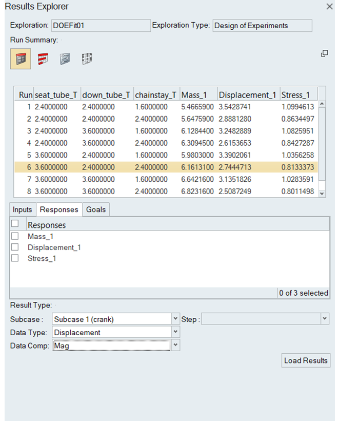
- Results Explorer
- Each of the aforementioned exploration types generates results, which
need to be viewed and interpreted. The results explorer provides an
interface for presenting exploration results, in the form of various
tables, plots, and charts to the user. It is also highly interactive,
allowing for interrogation and interpretation of the results.Figure 5.
- Solver Independence
- With the design explorer, explorations can be evaluated using either the OptiStruct or Radioss user profiles. All explorations are evaluated locally.
General
New Features
- Store and recall custom views
- The new Views tool enables you to save the current view of your model for future reference and recall saved views.
- Updates to the Element Quality View
- The Element Quality view now supports the Quality Index Range (QI Range) legend, in addition to the existing Criteria legend. The QI Range legend enables you to investigate the model with overall element quality categorized as Worst, Fail, Warn, Good and Ideal.
- Solid Core Geometry on Plies
- Solid geometry can now be used to define the shape of the ply. This geometry can be selected manually or come from external composite data. Upon ply realization, a drape table with thickness defined spatially is created for each ply with solid geometry.
Enhancements
- Auto update of contact surfaces after remesh
- This change will allow an auto update of contact surfaces when the underlying shell or solid elements are remeshed.
- Nodes selection using loop option on a washer
- You can now select one additional loop of nodes while creating rigids and rigidlinks on a washer.
- Direct option to select entities while using custom export option for self-contained includes
- New Select entities button allows you to go directly to the Entity State Browser while using custom export for self-contained includes.
- Contactsurf entities replaced by set segment
- The Contactsurf entity is no longer supported in HyperMesh 2020. All entities that used to refer to contactsurf are now found under the sets entity with the option Set Segment. All contactsurf entities present in older .hm files are automatically converted to segment sets. The migration is available for the following solvers: Radioss, OptiStruct, LS-DYNA, Nastran, Abaqus, and EXODUS.
Graphics and Visualization
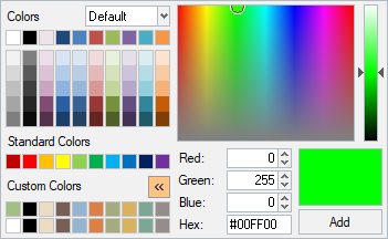
- New Color Selector and Full RGB Color Support
- Updated the color selector to utilize the full RGB (24-bit) color
spectrum. Click >> to display the custom color palette. This allows you
to create custom colors that can be used in the color selector.Figure 6.
- Transitions of Graphics Views and Functions
- Added support for visual graphic transitions from the model orientation view controls, delete, show/hide and isolate controls.
- Transparent Highlight Selection Support
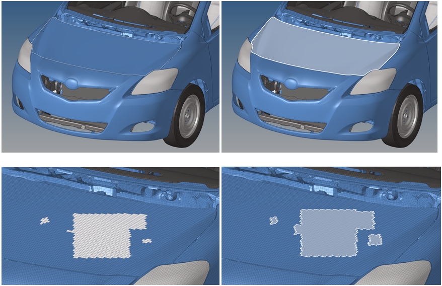
- Transparent highlight selection support adds visual enhancements to
allow users to better visualize the selected content while in a working
session for elements, components, surfaces and solids. Transparent
selection is off by default and can be turned on through the tab.Figure 7.
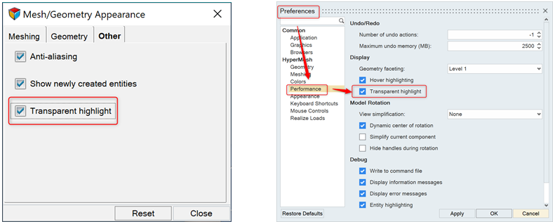 Figure 8. Original Selection and Transparent Selection
- Level of Detail Handling of Node Visualization
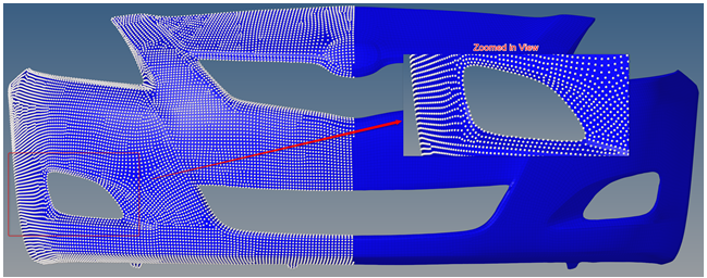
- Level of Detail (LOD) handling of nodes allows for more accurate node
representation with zoom levels and on models with complex and highly
refined meshes.Figure 9. Original Visualization of Nodes
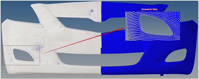 Figure 10. New Level of Detail Visualization of Nodes
Resolved Issues
- Element selection reset while performing translate after duplicating elements.
- Vector created using two nodes not displaying correctly while rotating the mesh.
- By group selection unable to find mid-side node.
- Preserving proper transformation while using position panel.
Geometry
New Features
- Tube Midline
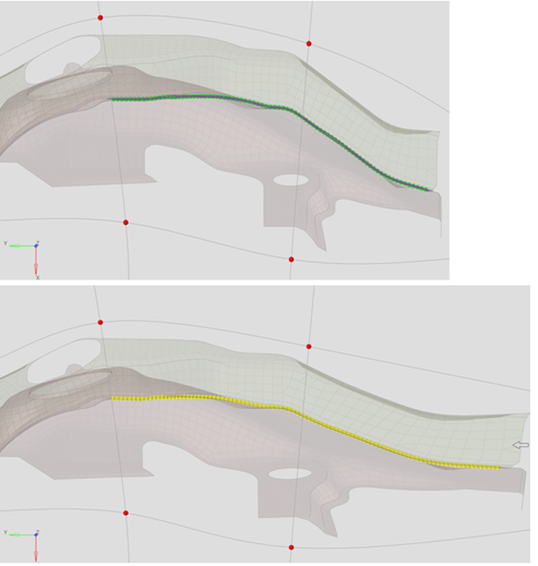
- A new API for generating midlines for solid tube geometries has been added. This is useful for generating lines that can be used as support for seam connectors, or for simplifying 3D geometries to 1D.
- Boolean
-

- Fillets
-

- Shapes and Lines
-

Enhancements
- Solids
-

- Split
-

- Undo/Redo
- All geometry APIs, panels and HyperWorks workflows are supported for undo/redo.
Resolved Issues
- Edge selection does not work while spherical clipping is on.
- Updating the pressure direction changes the magnitude of the pressure.
Miscellaneous
- The project > to surface subpanel now supports projecting to multiple surfaces.

Added a new "Generate plates only" option for the HyperWorks Midsurface > Automatic tool. If enabled, this will generate the plate information only without extracting the midsurface. This is useful when it is known ahead of time that a lot of plate editing will need to be done.
Added a new "Select Opposite" RMB option for the HyperWorks Midsurface > Automatic and Midsurface > Edit Plates tools. This allows for easy selection of opposite surface pairs.
Added support for nodes as input in the HyperWorks Drag tool.- Added support for nodes as targets for surfaces in the HyperWorks Imprint tool.
HyperWorks-Specific
New Features
- Locked/Unlocked Views

- Morph Shape Animation
- Animating Morph Shapes is now available inside the Shapes tool via the right-click menu, or the new Animate shapes toolbar button when selecting any number of Shapes. A new animation control toolbar allows playback control, as well as animation and contouring options.
- Quick Advancement Selection
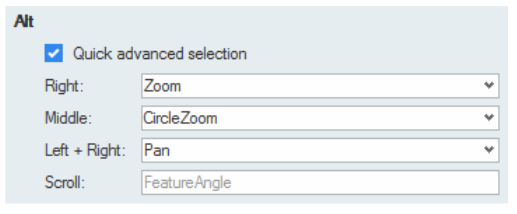
- New convenient access to select elements by faces and edges, nodes by
path, or lines by path by holding the Alt key during any selection of
these types. This new quick advanced selection method supports both
appending and deselecting. And in the case of elements by faces and
edges, it is now possible to quickly change the feature angle value by
using Alt + Scroll (mouse wheel). These new controls are turned on by
default, and are configurable in the Mouse Controls section of the
Preferences dialog. Figure 11.
Enhancements
- Move Tool Enhancements
- Improved transparency of arrows and rotators when selected, model fade effect during repositioning (using Shift or double click), and direction identification by adding X, Y, Z labels to the corresponding arrows.
- Free Morphing Enhancements
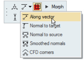
- When morphing to a target mesh or geometry, it is now possible to define
a custom projection direction by selecting the Along Vector option in
the microdialog, and using the provided interactive Vector Tool. Figure 12.
- Mesh Node Snapping Control
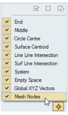
- A new control has been added to the Snap Options dialog to turn mesh
nodes snaps on or off. Figure 14.
- By Path Selection Preview for Nodes, Elements, and Lines
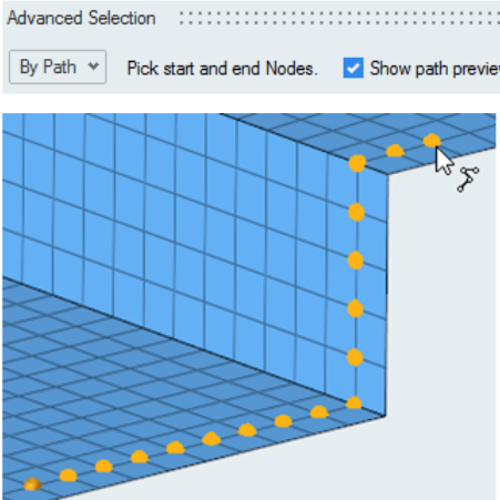
- A new Preview option has been added to By Path advanced selection method
for nodes, elements and lines. Turning this on will show a path preview
while hovering the mouse over selectable entities. This option is also
honored when selecting By Path using the newly added Alt keyboard
modifier. Figure 15.
- Context Menu
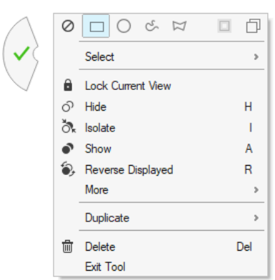
- The graphical context menu was overhauled and has support for more
entity types as well as new options. Display controls that were
previously only available inside idle mode are now available inside new
tools. The quick exit checkmark has been redesigned so it is more
difficult to accidentally trigger. Figure 16.
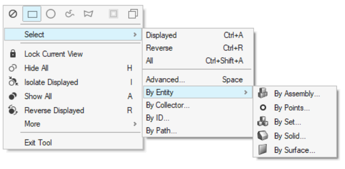
- Context Menu Advanced Selection
- All available advanced selection methods for any entity are now
available directly in the right-click menu. The default advanced
selection shortcut (Space) remains unchanged.Figure 17.
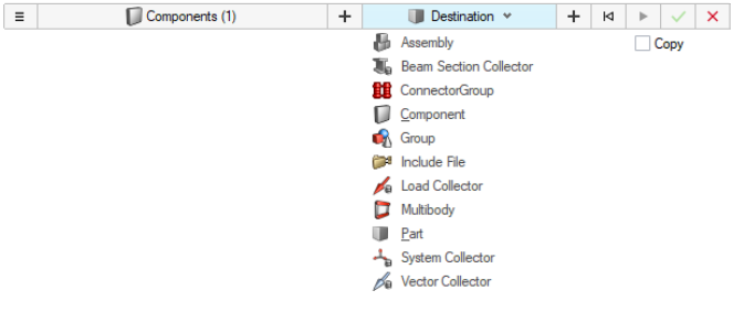
- Organize
- The new organize tool replaces the panel. It allows users to organize
entities into their respective collectors, includes, and parts. Figure 18.
- Theme
- There is a new default Gray color theme in 2020. Users can now also choose their graphical selection color via Preferences > Appearance > Selection color.
- Redesigned Coincident Picking Selection
- Coincident picking is now presented in a clearer list presentation that
gives the user information like name, color, ID, type. Additionally,
improvements to coincident selection graphics synchronization, tooltip
feedback, and large model performance are available. Figure 19.

- Remove non exported references
- When exporting a solver deck, references to any includes are always written to the master model even if the include itself is set to "Do Not Export."
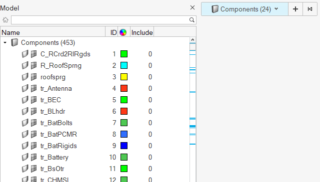
- Show selection indicators inside scrollbar
- The position of selected entities in the browser after selecting them
graphically is indicated by a blue marker inside the scroll bar.Figure 20.
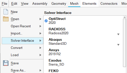
- File menu redesign
- A check mark is added to show the current solver interface when
switching.Figure 21.
Known Issues
- Model Browser on Linux
- Double-clicking on a folder in the Model Browser to change views will not work initially. Undocking and redocking the browser will fix the issue, as long as the browser is redocked by dragging and not by double-clicking on the undocked browser’s title bar.
LS-DYNA Interface
New Features
- New Keywords
- New keywords for LS-DYNA solver have been added in the following keywords groups: *CONTROL_IMPLICIT, *DATABASE, *DEFINE_FRICTION, *SET_SEGMENT
- New Friction Entity and Update in Contact Keywords
- *DEFINE_FRICTION_{OPTION} keywords are now supported in a dedicated entity and moved out from the Property entity type. Also, the assignment of the friction entity is enabled in the LS-DYNA contact keywords, with a new option in the entity editor.
- Solver Fields Names Export
- Only for LS-DYNA R11.1 solver profile, a new export option “Solver Fields Names” in export panel is added. This option is activated per default and enables to export all LS-DYNA keywords with the corresponding solver field names, which enhances the readability of the exported solver decks.
Enhancements
- Updated Keywords
- Existing keywords from keywords groups *CONTACT, *CONTROL, *DATABASE, *MAT_ADD, have been updated regarding latest LS-DYNA solver version.
- Parameter
- Duplicate parameter names are maintained, renaming the parameter name with suffix "_1" instead of ".1". Enabled curve ID parametrization in *CONTROL_IMPLICIT_EIGENVALUE.
- Model Checker
- Some improvements have been made in the LS-DYNA Model Checker: performances, checks coverage and new icons to start the model checker and perform all automatic corrections.
- Penetration Tool
- Added new "Minimum penetration depth" option to filter out penetrations having minimum depth values.
- Seatbelt System Tool
- A new feature in the Seatbelt System tool, allows to automatically generate cross-sections on the belt segments for post-processing of the loads in the belt after the simulation.
- Pre-Simulation Tools
- The update of the crash models after dummy or seat pre-simulation, by reading of the dynain file written in LS-DYNA Long format or i10 format is now enabled.
Resolved Issues
- Correction of SSTYP and MSTYP value when SSID or MSID is of type *SET_SEGMENT_GENERAL
- Removed redundant import warning message coming after reading MAT_077_H & MAT_077_O
- In the Penetration Check Tool, the penetration fix option “Fix penetrations (include pairs with shared nodes, if any),” accessible from the contact pairs context menu, is functional.
- Issue fixed during deletion of Positions from the Dummy Browser
- The algorithm for penetrations check on components selection in case the shell mesh size is smaller than the component thickness has been improved to avoid to report non-physical penetrations.
- *DEFINE_FUNCTION was not selectable for *LOAD keywords. This is now fixed.
- NSM attribute in *SECTION_BEAM is now considered in the mass calculation only for ELFORM value between 1 and 5.
- Importing a LS-DYNA model when ID=0 into loads or boundary conditions keywords was not possible. This behavior is fixed and next available ID will be automatically assigned.
- Export of *PARAMETER keywords order has been improved to avoid exporting parameters after the parameter expression they are referencing.
Marc Interface
New Features
- New Marc 2017 Version Supported
- Input decks of Marc 2017 version are supported. The legacy decks are all mapped to latest version on export.
- New Keywords
- New keywords MAT_GASKET,facemt/face supported.
Resolved Issues
- CONTACT BODY import and export issues fixed.
Model Build and Assembly
New Features
- Upload to PDM from Part Browser
- A new interactive workflow facilitates the direct upload of the HyperMesh BOM to Teamcenter.
Enhancements
- General Performance Enhancements
- Part Assembly and Part representation performance has been significantly improved for operations such as Save and Load.
- Instance Creation
- Part Instance creation on the import of PLMXML files is enhanced to support non-standard modelling practices in PDM.
- PLMXML Export
- The export of complete PLMXML BOM files is now supported.
- Representation Creation
- The creation of new Part representations is skipped if representations are available in the HyperMesh session. The Quality Report has been enhanced for the Common representation.
Resolved Issues
- Invoking the Criteria and Parameter Editor from the User Representation dialog resulted in an application error.
- HyperMesh Materials were not created upon generation of the Common representation if the PDM MID was not specified.
New Features
- Subsystem Browser
- A new system level model assembly workflow is available in HyperMesh via the Subsystem browser, which offers full support for representation, revision and configuration management.
Enhancements
- Loading from the Library
- Loading materials by name is now supported.
- Undefined Material Handling
- Saving an undefined material to the Library is no longer supported.
- Entity Management
- Entity Management of materials now supports names and IDs.
Resolved Issues
- Modified material density values were incorrectly shown in the Load from Library dialog.
- Material density was incorrect in the History tab of the Load from Library dialog.
- LS-DYNA materials color comments were not read on Load from Library operations.
Model Verification
Comparison
- New Features
- “Quick Compare” parameter is added to quickly check FEvsFE and review comparison results on HyperWorks graphics window. Match% are displayed in the graphics with legend where user can change color, scroll the slider to filter parts.
- Enhancements
- Sub Folder creation for variant model is not required for CAD vs CAD comparison.
- Resolved Issues
- Background and Interactive mode results were mismatching.
Verification
- Enhancements
- Spider pattern spring/1d elements are excluded in Spot Comparison check.
- Resolved Issues
- Assembly Name is missing in Intersection PPT file name if the “assembly-level” is set from config file.
Nastran Interface
New Features
- Element Addition
- Element type CQUADX4, CQUADX8, CTRAX3, CTRAX6 in Nastran NX profile
- New Material
- Material type MAT3 added in Nastran NX profile
Enhancements
- New Load Entities
- OptiStruct loads (SPC, FORCE, PLOAD,….) are
migrated to new HyperMesh entities. Along
with this implementation, user can now create loads from solver browser
and edit loads from entity editor. Some of the advantages with new load
management are below:
- Consolidation of loads by common attributes. For example, SID, Magnitude, etc.
- Interrogation of loads are much powerful. For example, Review, Vector plot, Contour.
- Advanced load option support:
- Apply pressure on nodes
- Apply traction on axisymmetric elements
- Apply pressure on 1D elements based on element orientation
- Solver Browser performance enhancements to handle large number of loads
- New Set Segment Entity
- Contact Surfaces entity is now migrated to the Set Segment entity. With this migration, the SURF/ELIST cards is now directly listed in the set segment entity.
- Remove include file reference based on export status
- HyperMesh only. When exporting a solver deck, references to any includes are always written to the master model even if the include itself is set to "Do Not Export."
Resolved Issues
- HM freezes while importing a bdf with more than one Super Element
- Incorrect Element System Visualization in Orientation Review
- Incomplete SUPORT card export while creating gaps from linear gaps tool in Aero profile
- Leading spaces in Case Control Section results in UNSUPPORTED cards on import
OptiStruct Interface
New Features
- OptiStruct solver feature enhancements
- This release includes critical enhancements from OptiStruct solver features released in 2019.1, 2019.2, 2020
- Explicit Dynamics Solution
- OptiStruct now supports Explicit Dynamics Solution. HyperMesh interface support includes OptiStruct Explicit Dynamics Solution. New HyperMesh entity Hourglass added to support HOURGLS card. This entity can be referenced in PSOLID/PLSOLID properties. Explicit time step TSTEPE add as load collector and this is referred in subcase selection TSTEPE in analysis type Explicit.
- Arbitrary beam section HYPERBEAM
- User can create arbitrary beam sections(Shell/Solid sections) from HYPERBEAM and assign to PBEAML/PBARL. Once assigned these beam sections will be exported as OptiStruct arbitrary beam section format.
- VABS Input generation
- HyperMesh can now generate input for VABS (Altair partner product). This is supported in OptiStruct Aero profile, Under Beams from lines tool.
- Cohesive modeling
- Cohesive elements can be modeled with penta first/second order (CIFPEN, CIFPEN) or hexa first/second order (CIFHEX, CIFHEX) solid elements. Corresponding cohesive material and property are supported as well. Cohesive modeling with damage is supported as new entity called ‘DAMAGE’ which supports damage initiation and damage evolution.
- Edge to Edge contact for solids
- Keyword “PSURF” is added as continuation line in CONTACT bulk data. PSURF continuation line will reference PSURF bulk data ids.
Enhancements
- Compute inertia and mass properties using OptiStruct
- Added new option in Tools pull down under Mass details to calculate mass properties from OptiStruct solver. You need to have solver executables installed to access this feature. The required information will be available from .hmcheck ascii file which is parsed by HyperMesh and showed in Mass details summary.
- Migration of TABLEx cards to Curve entity
- All the TABLEx cards are now mapped to curve entity. You can visualize multiple curves through curve editor. Additionally, you can import curve data from external files and export to .csv format as well.
- Symbolic Substitution
- Symbolic substitution provides flexibility to modify the input file to use parameterized input to define various data fields across the model. Currently, only real-valued data fields of entries in the bulk data section are supported for parameterization using symbolic substitution. Parameter entity is used to parameterize real value fields in Property and Material cards. Refer to the OptiStruct documentation for more details.
- Fatigue Analysis
- Fatigue process manager template enhanced with the following
features:
- Allow to update SN, spot & seam weld material properties into the same material
- Plot SN Curve function should be updated for spot & seam weld types
- Revamp UI for defining fatigue mat & prop data
- Add support for all weld types when creating FATSEAM card
- Support XGSET & XGRID attributes for FATDEF card
- Modal Results Output
- New entity ‘Modal results output’ added to support MODOUT solver card
- Imperfection
- The IMPERF Bulk Data and Subcase Entries can be used to apply an
imperfection. An imperfection can be introduced into the model in the
following ways:
- TYPE=H3DRES on IMPERF Bulk Data: An h3d file is referenced which contains previously completed analysis results.
- TYPE=GRID on IMPERF Bulk Data: The perturbation of grids can be directly applied.
- Node to node contact
- New Contact discretization type, Node to Node (N2N), is now supported. Slave/master of CONTACT Bulk Entry should be grid set.
- Results output during job runtime for Nonlinear Analysis
- With the presence of NLOUT Bulk/Subcase Entry, PARAM,IMPLOUT,YES/NO will allow you to turn on or off the output of results output during the job run time for nonlinear analysis.
- OSSMOOTH Enhancements
- OSSMOOTH enhanced to export geometries in JT format.
- New Load Entities
- OptiStruct loads (SPC, FORCE, PLOAD, etc.)
are migrated to new HyperMesh entities.
Along with this implementation, you can now create loads from solver
browser and edit loads from entity editor. Some of the advantages with
new load management are below:
- Consolidation of loads by common attributes. For example, SID, Magnitude, etc.
- Interrogation of loads are much powerful. For example, Review, Vector plot, Contour.
- Advanced load option support
- Apply pressure on Nodes
- Apply Traction on axisymmetric elements
- Apply pressure on 1D elements based on element orientation
- Honoring solver recommendation. For example, Load on set.
- Solver Browser performance enhancements to handle large number of loads.
- New Set Segment Entity
- Contact Surfaces entity is now migrated to the Set Segment entity. With this migration, the SURF/ELIST cards is now directly listed in the set segment entity.
- Updated Keywords – PARAM card
- PARAM,IMPLOUT allows an _impl.h3d to be available while the job is running.
- Remove include file reference based on export status
- HyperMesh only. When exporting a solver deck, references to any includes are always written to the master model even if the include itself is set to "Do Not Export."
Resolved Issues
- HyperMesh freezes while importing a bdf with more than one Super Element.
- When you add a barrier mesh component in the free shape variable, the BMESH flag isn't exported
- Segmentation error while using Ossmooth feature in FEA reanalysis with remesh option.
- Fails to import input file with long user comments written from competitor preprocessor.
- Neuber correction was missing in region identifier options in Entity Editor for static stress response.
- Segmentation error while running OSSMOOTH to get STEP geometry.
PAM-CRASH 2G Interface
New Features
- New PAM-CRASH 2G 2019 Solver Version
- PAM-CRASH 2G 2019 solver profile is introduced.
- New Entity for Seat Belt Keywords
- Enhancement offered for the support of the PAM-CRASH 2G keywords RETRA / & SLIPR /.
- Undefined Parameters
- Parameters PYVAR and PYFUNC referenced into keyword fields, but not defined in the input deck will be managed by the automatic creation of undefined parameters to retain references in the input deck.
- New Keywords
- New keywords DMPEW, MACTRL, REQUIRE_PRECISION, REQUIRE_VERSION, SELOUT and sub keyword OGRP have been added.
Enhancements
- Updated Keywords
- Updated keywords ANALYSIS, UNIT, CNTAC Type 44, MATER (2018). Enabled direct creation of GROUP (set of set) keyword and extended listing of SENSOR and SECURE keywords from Solver Browser, Create Cards from Tools menu & Quick Search Tool (CTRL+F).
- Parameters
- Support of nodal XYZ Coordinates parameterization for import and export. However, no edit or listing in browser. IDNOD field parameterization not yet supported.
- Penetration Tool
- Added new "Minimum penetration depth" option to filter out penetrations having minimum depth values.
- Model Checker
- Added new checks into model checker for the model validation.
- Seatbelt Browser
- Added provision in seatbelt browser which enables quick creation of RETRA, SLIPR and SECFO on seatbelt segment.
- Removed Tools and Features
- Removed tool “Org: By Plink Part” of “Connector organize” from page “Conn” under utility menu.
Resolved Issues
- PART_TIED referred in TIED contact are excluded from empty check.
- Removed unnecessary import warning messages with keywords PYVAR, PYFUNC, CNTAC types 36, 37, 46 and RBODY.
- The legacy format TETRA elements converted to new format TETR10 upon import.
- It is possible to import the long file name (<256 character including "INCLU / " keyword) as Include file name or path on same line.
Permas Interface
New Features
- AutoContact Support
- The following contact cards can be created automatically based on the
selected slave and master:
- CONTACT_SURFACE_SURFACE
- CONTACT_SURFACE_SURFNODE
- CONTACT_SURFACE_NODE
- CONTACT_NODE_NODE
Radioss Interface
New Features
- Support of Radioss 2020 Version
- New Keywords
- New keywords from Radioss solver version 2019.2 and version 2020 for /ANIM, /FAIL and /MAT keyword groups have been added.
- Support of Undefined Parameters
- Parameters which are referenced in a Radioss keyword but not defined in the input deck are maintained in the HyperMesh session and represented as undefined.
- New Friction Entity
- The new Friction entity is used to support the Radioss keyword /FRICTION which allows to define a specific friction model between parts or set of parts in contacts.
- New Loads Entities
- All Radioss loads (/BCS, /GRAV, /INIVEL, /IMPVEL,….) are migrated to new HyperMesh entities, having their own Pool-IDs which avoids ID conflicts and automatic renumbering during Radioss model import process. The new loads entities have a dedicated vector or contour display. Along with this implementation, the Radioss BCs Manager has been removed.
- New Set Segment Entity
- The old Contact Surfaces entity is now migrated to the Set Segment entity. With this migration, the /SURF/SEG Radioss keywords are now directly listed in the surface SET selection, with all other /SURF types.
Enhancements
- Updated Keywords
- Existing keywords from keywords groups /ALE, /MAT, /PROP and /RBODY have been updated regarding Radioss solver version 2019.2 and version 2020.
- Export of Keywords with Solver Field Names
- As part of a new development for the support of the solver keywords, all Radioss Material cards are now exported properly with all solver field names.
- Model Checker
- Some improvements have been made in the Radioss Model Checker: performances, checks coverage and new icons to start the model checker and perform all automatic corrections.
- Penetration Tool
- Added new "Minimum penetration depth" option to filter out penetrations having minimum depth values.
- Seatbelt System Tool
- A new feature in the Seatbelt System tool, allows to automatically generate cross-sections on the belt segments for post-processing of belt loading.
- Dummy Browser
- The dummy positioning tool supports now Radioss dummy models with /PROP/KJOINT2 joints definition.
- Remove include file reference based on export status
- HyperMesh only. When exporting a solver deck, references to any includes are always written to the master model even if the include itself is set to "Do Not Export."
- Mass Calculation
- The entity state of the Solvermass entity is now considered for the mass calculation. When it is OFF, the lumped mass added by the corresponding /ADMAS keyword is ignored.
Resolved Issues
- During model import process, the wrong Warning message referencing to the Engine file is now corrected.
- Issue fixed during deletion of Positions from the Dummy Browser.
- Some invalid checks in the model checker have been removed.
- Import warning for engine file not found has been corrected in order to appear only when it is valid.
Solid Meshing
New Features
- Multiple normal for boundary layer
- A new implementation for generating boundary layers with multiple normal. There is no limit on angle and you can select the nodes or lines on which to generate boundary layer. It is defined based on feature angle, and will auto append selection if required. You can also define sweep angle for multiple normal.
- Solid map mesh controls
- New mesh controls are added for solid map. Along with Tetra or boundary layer + tetra, you can create solid map mesh controls. This will enable you to generate hybrid hexas and tetra mesh. Also enables you to define different controls for different solids and execute meshing in one go.
- Element connection APIs
- New *solidrc APIs are added to connect overlapping and intersection components. Useful multi-threaded APIs to connect overlapping and intersecting parts.
Enhancements
- Boundary layer side and volume meshing order
- A new option added in local boundary layer mesh control to select the side of interface surface on which boundary layer is required to grow. If a surface is shared by 2 volumes, you can define on which side boundary layers are required. For multiple volume meshing cases, new logic is added to automatically choose the order of volume to be meshed to have maximum boundary layer coverage.
- Thin solid
- Thin solid functionality is improved to handle parts with tiny slots. Robustness improved in general. A new option added to automatically fix quality of generated hex. This will create valid high quality hex mesh for thin solids.
- Undo/Redo
- All solid meshing capabilities such as tetrameshing, boundary layer meshing, solid map, etc., have undo/redo support.
- Minimum height input in tetra meshing
- Now you can define constraint for minimum height for tetra meshing. For Delaunay mesher type, if minimum height is defined, algorithm attempts to enforce the minimum height during meshing.
- Miscellaneous
- Support of quad element input for hex dominant meshing.
