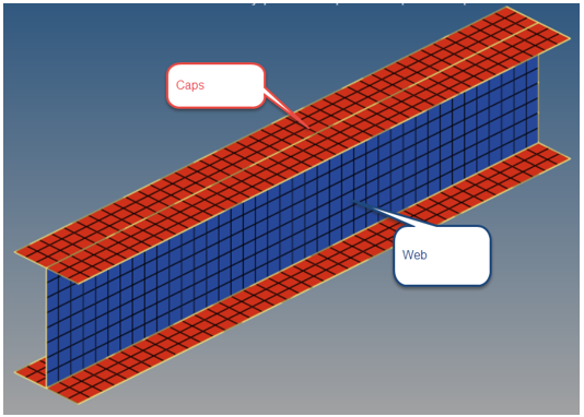
Step through the model build process for a composite I-beam model.
Interface laminates and sublaminates will be demonstrated. You should complete the Composite Analysis tutorial first. The steps required to define a ply-based
laminate on complex geometry with T connections include:
Ply creation
Set ply normals
Sublaminate creation
Interface laminate creation
Template property creation
The analysis model includes:
Surface geometry and mesh of I-beam
Orthotropic material
System collector that contains system used to assign material direction
Unit system is PSI
The manufacturing process uses complex tooling to manufacture 4 sublaminates
(co-cured to form the final part):
top cap on Tool 1
bottom cap on Tool 4
left web on Tool 2
right web on Tool 3
Figure 1.
Figure 2.
Review Stacking Direction and Element Normals
Review stacking direction and element normals.
Open HyperWorks Desktop.
In the User Profiles dialog, set the profile to OptiStruct.
Open the model file, composite_beam.hm.
Open the composites panel by clicking 2D > composites > element normals.
Toggle from color display to vector
display and click display. This will
display the current element normals for displayed 2D elements.
Note: For typical ply-based models with T junctions, cap element normals should
point away from the web. Web element normals are arbitrary as long as the
direction is consistent. Confirm that the element normals of the cap
elements point away from the web and that web element normals point in the
direction of global y.
Figure 3.
Review Material Orientation
Review the assigned material orientation.
Open the composites panel by clicking 2D > composites > material orientation.
Select the component on which material orientation will be reviewed by setting
the middle top collector to comps and then selecting the
ibeam component.
Click review to plot the current material orientation.
The material orientation for this part has already been defined as the x
direction of the local system with id = 1.
Figure 4.
Create Plies
Create the plies that make up the composite laminate.
In the Model Browser, right-click in white space and select Create > Ply from the context menu.
Create the plies according to the table below. Notice that shapes are used in
this laminate and are described in the image below of the I-beam cross section.
Each shape should be the full lentgth of the beam.
Ply Name
Ply ID
Material
Thickness
Orientation
Shape
ply1
1
M40J
0.01
90
Top_cap
ply2
2
M40J
0.01
0
Top_cap
ply3
3
M40J
0.01
45
Left_web
ply4
4
M40J
0.01
-45
Left_web
ply5
5
M40J
0.01
90
Center_web
ply6
6
M40J
0.01
45
Right_web
ply7
7
M40J
0.01
-45
Right_web
ply8
8
M40J
0.01
0
Bottom_cap
ply9
9
M40J
0.01
90
Bottom_cap
Figure 5.
Set Ply Normals
Correct ply normals.
In models with T junctions that are modeled using a ply-based method, plies on each
side of the web will have opposite stacking directions. On one side, the element
stacking direction will be consistent with the cap, and on the other side it will
not. See the image below.
Figure 6.
The discontinuity in stacking direction on the left side of the I-beam model will be
corrected using ply normals. Ply normals manipulate the direction that an individual
ply stacks.
Note: When ply normals are changed, a DRAPE table is created and assigned
to the ply.
From the menu bar, click Tools > Orientation Review > Ply normals.
Toggle the Select ply arrows so that ply3 is
active.
Click Apply to plot current
ply normals. Note the discontinuity described above.
To correct ply normals, click the Pick elements > Elements collector twice to access the element selection panel.
Select only elements of the web and click
proceed.
Click the Reverse radio button under Normals and then
click Apply. This will plot
corrected ply normals for ply3.
Reset the Display radio button under Normals to prevent
any additional changes.
Confirm the web of ply3 has no discontinuity with the caps by repeating Step 2
and Step 3.
Repeat Step 3 through Step 8 for ply4.
Create Sublaminates
Create the laminate. This stacks the previously created plies.
In the Model Browser, right-click in white space and select Create > Laminate from the context menu.
Under Type, select Sublaminate.
Under Name, type top.
Populate the ply table with ply1 and ply2.
Click Create.
Repeat Step 1 through Step 5 for the left, right, and bottom sublaminates
according to the images below.
Figure 7. TopFigure 8. Left
Figure 9. Right
Figure 10. Bottom
Create Interface Laminate
Create the interface laminate, which specifies how the sublaminates are
joined.
The interface laminate contains a list of sublaminates. It also contains a list of
interfaces that specify how sublaminates connect (interface) with each other. Each
interface definition contains two inputs: interface ply1 and interface ply2. These
are either the top most or bottom most ply of each sublaminate that interface. The
order they are entered is the order the sublaminates are stacked, in the direction
of the element normal. See the figure below for the correct interfaces for the
I-beam.
Figure 11.
In the Model Browser, right-click in white space and select Create > Laminate from the context menu.
Under Type, select Interface Laminate.
Under Name, type interface.
In the sublaminate table, click in white space in the Sublaminate
name column and select the top
sublaminate from the list.
Add the left, right, and bottom sublaminates using the same method.
Note: Five interfaces are required for the I-beam.
Right-click in white space and select Add Interface.
Create the 5 interfaces in the Interface definition table at the bottom of the
dialog.
Define Interface ply1 and Interface
ply2 for each interface using the values in the previous
image.
Click Create to create the interface laminate.
Figure 12.
Create Ply-Based Properties
Create two PCOMPP ply-based properties.
Typically, only one ply-based property is required per part. However, for cases where
portions of a part require different property attributes (offset is most common),
multiple properties are required. For the I-beam model, the elements that make up
the web are at the midplane of the laminate, and the elements that make up the caps
are at the tube tooling surfaces.
In the Model Browser, right-click on white space and select Create > Property from the context menu.
Set Card Image to PCOMPP.
Set Name to caps.
Set Z0 to 0.0. This defines the offset such that plies
begin stacking from the location in space of the elements.
Assign the elements of the caps by right-clicking on the property in the
Model Browser and selecting
Assign from the context menu.
Figure 13.
Repeat Step 1 through Step 3 for the web property. Leave Z0 as blank.
Assign the elements of the web by right-clicking on the property in the
Model Browser and selecting
Assign from the context menu.
Figure 14.
Figure 15.
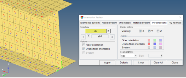
Optional: Ply Direction Visualization
Plot vectors that represent the ply1 and ply2 directions on each element.
From the menu bar, click Tools > Orientation Review.
Select the Ply directions tab.
Click Apply.
This will plot the ply1 and ply2 directions for the current ply in the
list.
To scroll through plies, click the << or
>> icons under Select ply.
For ply3 and ply4, which have corrected ply normals, activate the
Drape fiber orientation option.
Figure 16.
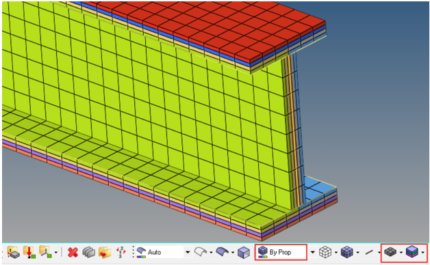
Optional: Composite Layers Visualization
Visualize the thickness and ply layers of the laminate.
Set Element Representation to 2D Detailed Element
Representation. This will visualize the total thickness on each
element.
Set the Composite Layers control to Composite Layers.
This will display the individual layers within each element thickness.
Change the Element Color Mode to By Prop. This will
color each layer by the color of the ply.
Recolor plies by shift selecting all plies in the ply folder, selecting one of
the color icons, and clicking Auto color.
From the menu bar, select Preferences > Graphics and type 5 in the ply visualization
thickness factor input. This will temporarily increase the displayed thickness
of each ply layer for the purposes of visualization.
Confirm that all plies are in the expected order. If the interfaces were
defined incorrectly, there will be discontinuities where portions of a ply jump
to an unexpected location in the full stack.
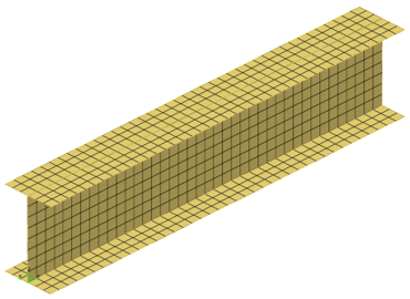
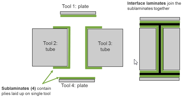
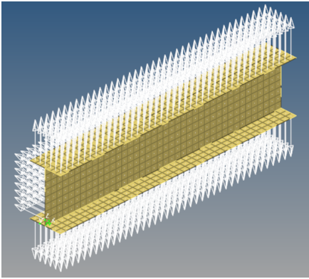
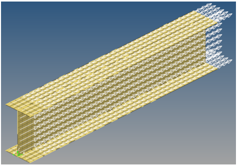
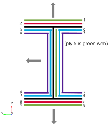
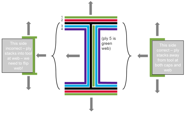
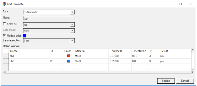
 Figure 9. Right
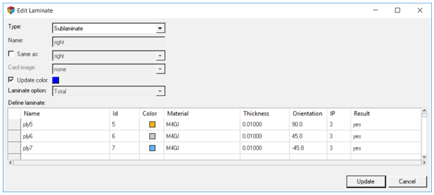 Figure 10. Bottom
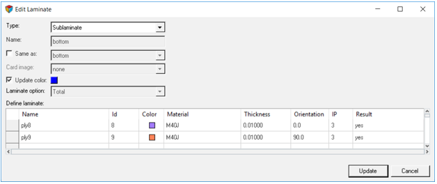
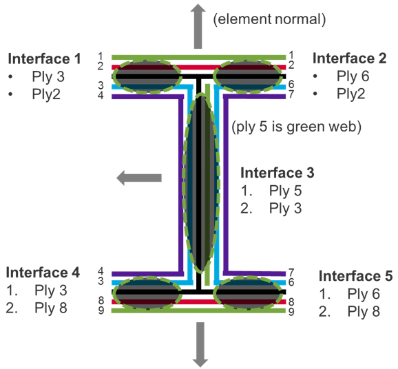


 Figure 15.