Pedestrian Impact
The Pedestrian Impact tool automates the vehicle marking, impactors positioning and the export of solver decks with minimal input, therefore reducing the full process lead time.
The tool conforms to the pedestrian safety regulations EuroNCAP, CNCAP, UN-R127 and GTR.
From the menu bar, click .
- The vehicle is positioned with its centerline on Y=0 plane and oriented in the -X global direction.
- The initial position of the impactor is in the +X global direction and CoG at global (0;0;0) coordinates.
- The master files for each of the impact load cases need to be prepared in advanced with the necessary include files, except for the impactor include.
The Pedestrian Impact tool automatically exports the master file for each of the selected impact points and automatically adds the impactor include file and the transformation cards.
Vehicle Marking
- The Protocol Inputs
- Regulation: Select one of the supported regulations.
- Impactor: Select one of the following:
- Headform: Child and adult head impact
- Legform: lower-leg and upper-leg impact
- All: Perform all impact load cases
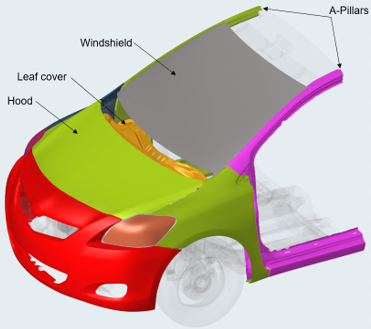
- The vehicle componentsFigure 1. Vehicle Outer Surfaces
- Bumper Beam: If leg form impact points have to be created, select the Bumper Beam
components.Figure 2. Bumper Beam Components
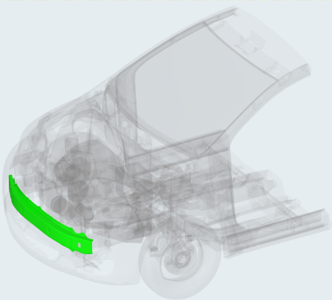
- Bumper Beam: If leg form impact points have to be created, select the Bumper Beam
components.
- The ground definition: For the marking process, you must define the ground level,
which gives the reference level of the construction lines. Below are the different
options that are available.
- Ground Type
- Flat: The ground is flat with normal in Z direction. You can specify the Z distance manually or select a node on the graphic.
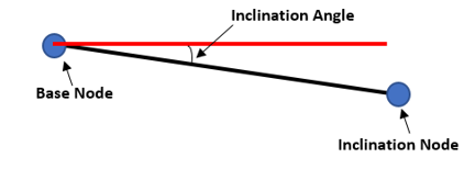
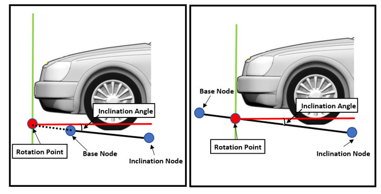
- Inclined: The ground level can be specified by selecting two nodes or
providing coordinates manually for Base node and Inclination node. The rotation
of the ground is then automatically calculated based on the coordinates of the
nodes.
- Inclination Type: Base Node: The rotation is calculated around the
provided base node.Figure 3.
- Inclination Type: Forward Rotation: The rotation point position is
automatically defined on the front of the vehicle.Figure 4.
- Inclination Type: Base Node: The rotation is calculated around the
provided base node.
- Ground Type
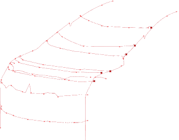
- Created Marking Entities: The Pedestrian Impact tool automatically generates:
- Testing Area Lines
- Wrap Around Distances lines (WADs)
- Left and Right Bonnet Side Reference lines (LSR and RSR)
- Bonnet Leading Edge (BLE)
- Bonnet Rear Reference Line (BRRL)
- Upper Bumper Reference line (UBR)
- Lower Bumper Reference line (LBR)
- Internal Bumper Reference line (IBR)Figure 5.
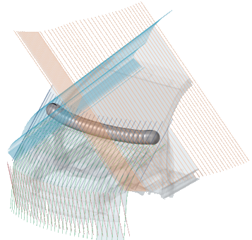
- Construction lines and spheres used to create the Test Area Lines:Figure 6.
- Tape components that are used to close the openings at the front of the vehicle
and in the gap between the windshield and hood:Figure 7.

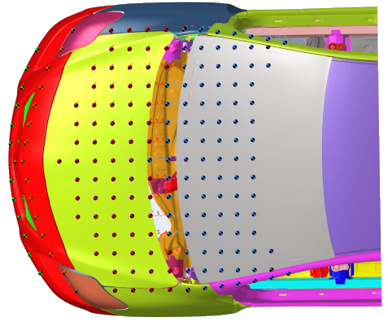
- Impact Points for the selected load cases (Headform, Upper-Leg, Lower-Leg). The
impact points are stored as design point entities in the Model Browser. Each impact point has its own graphic and name defined
as per the regulation protocols.Figure 8.
- Testing Area Lines
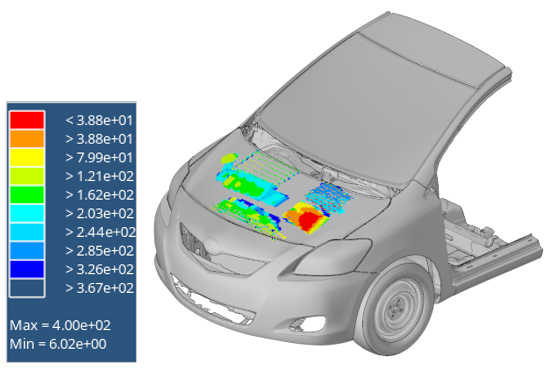
Hard Parts
The Hard Parts tab allows you to plot a distance distribution on the hood or front of the vehicle in order to identify the critical areas of impact for the head and leg.
Positioning

- Inputs
- Velocity units for upper legform: Since upper legform velocity is calculated by the tool, it is necessary to provide the correct unit system to be used for this load case. Other load case velocity inputs are fixed and directly referenced with a dedicated include in the master file.
- Adult Headform/Child Headform/Upper Leg/Lower Leg: Import the corresponding impactor input deck. For each impactor, the components that need to be considered for the positioning can be changed using the components selector.
- Vehicle Outer: Same functionality as in the Vehicle Marking tab.
- Wiper Blades: Select the components of the wiper blades in order for them to be considered in the positioning of the headform.
- Deployable Hood: Select the deployable hood components.
- Impact points
- Search filters: Filter and retrieve a specific impact point or a load case group of impact points.
- Impact points table: Provides access to all of the impact points that the tool generates. The Active and Export status can be managed as well as the display status from the context menu.
- Export filter: A selection for load case impact points for the export, instead of changing them one-by-one using the Export status of the impact points in the table. Clicking Preview allows you to visualize the position of the selected impact points in the table.
- Export options
- Adult Headform/Child Headform/Upper Leg/Lower Leg: Import the corresponding master file for the export of the selected impact points. Click Preview Deck for a preview of the loaded master file.
- Master out directory: Specify a local directory where all of the selected impact points folders and master files will be written.
When all of the export set up is done, click Export to start the automatic export of solver decks for the selected impact points.
Export Solver Decks
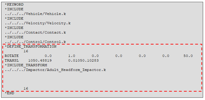
- LS-DYNA
- The impactor include file is defined as an *INCLUDE_TRANSFORM and the
*DEFINE_TRANSFORM cards are automatically generated and assigned to the
*INCLUDE_TRANSFORM.Figure 11.
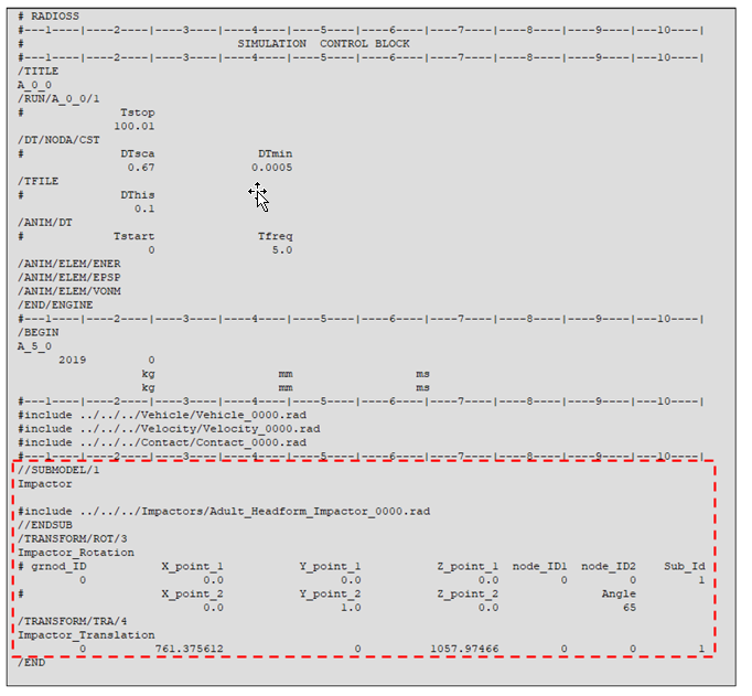
- Radioss
- The impactor include file is defined in a //SUBMODEL and the /TRANSFORM cards are automatically generated with reference to the impactor sub model.
-
Note: The master file must be written in the single input format.Figure 12.