Free Morph Mesh
Use the Free Morph tool to morph mesh by moving nodes, faces, and edges or by mapping to geometry.
-
From the Mesh ribbon, Morph tools, click the Free Morph tool.
Figure 1.

- Optional:
On the guide bar, click
 to define morphing options.
Free Morph Tool
An overview of the Free Morph tool.
Use the Free Morph tool to morph mesh by moving nodes, faces, and edges or by mapping to geometry.
- Access
- Go to .
Guide Bar Options
- Automatic
- Automatically select anchor nodes and morph area elements.
- Remorph changes
- Re-applies previous morph with new options and entities.
- Automatic anchors
- Enables automatic selection of anchor nodes.
- Calculate by
- Select fixed nodes.
- Value
- Set distance or multiplier.
- Morph method
- Select method to morph mesh.
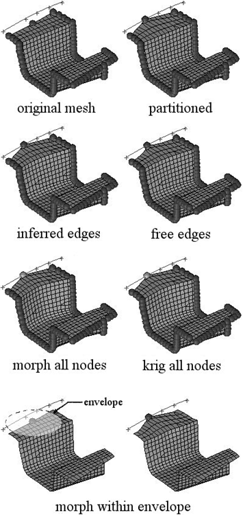
- Figure 4 shows how the different methods affect the mesh morphing. For the
partitioned option, the inner edge closest to the moved nodes is
unaffected since an edge domain is internally created for it. For the
inferred edges option, no inner edges were created and thus the inner
edge ends up curved as its nodes follow the moving nodes. For the free
edges option, no outer edges were created either and thus the outer
edges end up curved as well as the inner ones. For the morph all nodes
and krig all nodes options, note the differences in the methods,
especially the smoothness of the kriging algorithm. For the morph within
envelope option, note how the mesh inside the envelope is linearly
perturbed relative to the distance from the moving node and that no
fixed nodes are required.Figure 4. Example: Edge Bounding
- Undisplayed nodes
- Select option for undisplayed nodes.
- Moving nodes
- Set bias for moving nodes.
- Anchors
- Set bias for anchors.
- Translate increment
- Enables discrete movement of manipulator in translation.
- Rotate increment
- Enables discrete movement of manipulator in rotation.
- Step size
- Increment for translating/rotating multiplier
- Real time
- Morph mesh while moving manipulator.
- Active
- Allow manipulator to morph mesh.
Mapping Options
Use the following microdialog options when selecting target geometry.
 - Use
manipulator
- Use
manipulator- Move entities interactively with the Move tool.
 - Projection
direction
- Projection
direction-
- Along vector
- Project along a user-defined direction using the Vector tool. After a direction is defined, press ESC to close the tool.
- Normal to target
- Project normal to target.
- Normal to source
- Project normal to nodes' mesh.
- Smoothed normals
- Calculate the average normal direction for all elements and then smooth them so that transitions near corners are not abrupt.
- CFD normals
- Use a sophisticated algorithm to smooth the normals for all the elements such that the elements will not get folded when their nodes are morphed.
- Fit to line
- Fit along line through target.
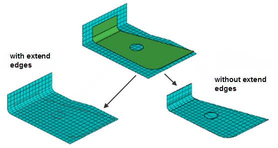
 - Toggle extended
surface edges
- Toggle extended
surface edges- Extend the edges of the surfaces or mesh in a direction perpendicular to the normal at the closest point on the surfaces or mesh. If this option is selected, the moving nodes will be projected on to an extended representation of the surfaces or mesh, enabling you to project nodes beyond the edge of the surfaces or mesh as well as within any holes. If this option is not selected, the moving nodes will be projected on to the interior or edges of the surfaces or mesh, which may end up distorting the morphed mesh.
- In Figure 5, three surfaces are floating above an angled mesh. All of the nodes of
the mesh are selected as moving nodes and they are projected to the surfaces
in the normal to geom direction. With extend surface edges selected, the
moving nodes are moved either to the surfaces or to virtual surfaces which
extend perpendicular to the normal direction at the edge of the surface.
Note how the nodes end up placed inside the hole in the center of the
largest surface. Without extend surface edges selected, the moving nodes are
moved to the nearest point of the surfaces. Note how several layers of
moving nodes end up compressed at the edge of the surfaces and around the
edge of the hole.Figure 5.
 Note: Available when elements are the target entity.
  - Offset
- Apply an offset value to be maintained between the moving nodes and the
selected targets. This value represents an absolute distance, regardless of
the direction in which the nodes are moved.
A positive value for the offset will place the nodes short of the target, a negative value for the offset will place the nodes beyond the target, and an offset of zero will place the nodes on the target.
When mapping to target elements, the direction of the offset will be calculated using the element normals.
 - Offset in all
directions
- Offset in all
directions- Measure the offset from each node to the closest point on the target,
regardless of projection direction.
When turned off, the offset is measured along the direction of projection of each node.
 - Autofix target normals
- When mapping to target elements, this option will ensure all mapped nodes remain on the same side of the target mesh by automatically adjusting any flipped normals in the target mesh.
Keyboard Shortcuts and Mouse Controls
| To do this | Press |
|---|---|
| Undo morphing | Ctrl + Z |
| Undo all morphing operations | Ctrl + Shift + Z |
| Redo morphing | Ctrl + Y |
| Redo all morphing operations | Ctrl + Shift + Y |