Additional Aerospace Tools
Expand the sections below to learn more about the Additional Aerospace Tools.
This functionality allows total loads (forces and moments) to be applied in a distributed manner on nodes even though the load is applied on geometry lines or set of nodes forming ordered edges. This feature is available in the Nastran and OptiStruct solvers in the Aerospace user profile and is accessed by clicking BCs > Create > Line loads or by clicking Aerospace > Loads/BCs > Line loads.
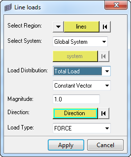
You can provide the total force or force/unit length. The program first calculates the force per unit length from the total force and length of the lines (or total node distances in case of node path). Then based on the nodal distance and the shape functions of the elements, it distributes this 1D pressure (force /unit length) evenly to the nodes within the element edge.
- Select the geometry lines or the orderly picked node path.
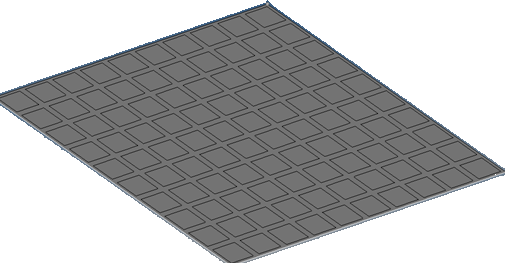
The list of geometry surface edges/lines can be selected
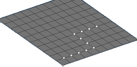
The list of nodes can be selected in an ordered sequence
The order of picking of the nodes or lines forms the edged used to calculate the total length of the segments. - Select the system on which the loads will be applied (global or user defined).
- Select the Load Distribution type (total, unit length or constant).

- Total Load: This total load will be uniformly distributed based on uniform pressure to the element nodes based on the order of the elements (liner or quadratic-mid nodes).
- Load per unit length: You can directly provide the 1D element pressure.
- Constant load: This option takes the load you provide and applies it to each node with the same magnitude entered in the dialog.
- You can also select component magnitudes separately if you do not want to use the vector option (Constant Vector - single magnitude or Constant Components x,y,z values).
- Enter the load magnitude depending on the load distribution type.
- Select the Direction vector if the load type is constant vector.
- Indicate the force or moment.
- Click Apply.
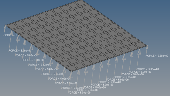
Total load is distributed to nodal forces based on the element edge length and order of the element. The summation of the loads should match the total load applied.
This tool is used to connect two dissimilar 2D shell meshes using RBE3 connection. If the nodes are really close to each other within a tolerance they will snap without creating the RBE3 connection.
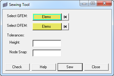
- Select the global finite element model (GFEM). The free edges that need to be connected will be displayed.
- Select the detailed finite element model (DFEM). The free edges that need to be connected will be displayed. The Height and Node Snap tolerances will automatically be calculated. You can change these.
- Click Sew. This will connect the 2D shell meshes using RBE3 connection.
Note: Height is the cordial height difference between GFEM and DFEM models. RBE3 is not created if the height is more than the height tolerance that you provide.
Note: Global finite element models are coarse FE models with shell and beam elements for internal loads calculation.
Note: Detailed finite element models are fine models, mostly with shells and solids with finer mesh for detail strength calculation.
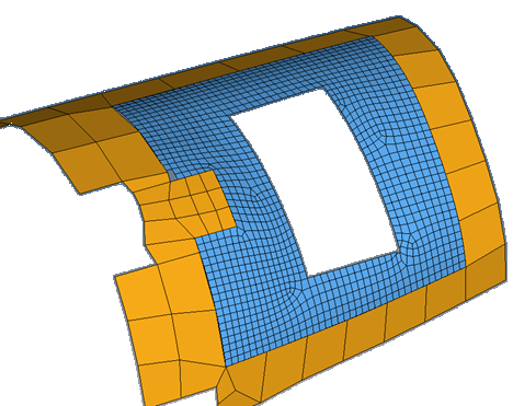
Coarse (GFEM) and fine (DFEM) mesh
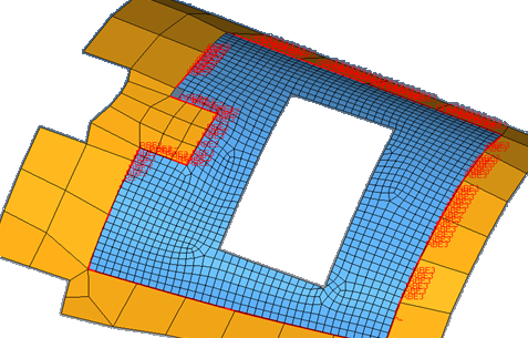
RBE3 connection only on the two free edges of the GFEM and DFEM element sets
The Rutman connection and Huth formula connection are supported with the Fastener Setup tool, which is available in the Aerospace OptiStruct and Nastran user profiles.
Huth Formula Connection
Use this tool to connect two shell components using a special aerospace commonly used connector known as the Huth formula. This formula depends on if the components are composite or metallic. Roll your mouse over the various fields to learn more about each field using the Huth Formula.
Rutman Fastener Connection (HI-LOCK)
Using this method, rivet locations can be input from a .csv file or from line data from a CAD system representing the fastener location. The CSV rivet location file format is shown below (diameter x,y,z of the top location of the rivet, x,y,z of the bottom location of the rivet and the material name).

Roll your mouse over the various fields to learn more about each field using the Rutman Fastener Connection.
The Spatial Renumber tool is used to renumber the rectangular regular array of elements or quads in two perpendicular directions in a user defined coordinate system (Cartesian or cylindrical). A local coordinate system must be created to match the two primary numbering directions.
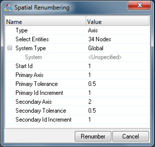
First we need to select a list of nodes or elements to be renumbered. After we select those, we need to select a local system. The global system ID=0 cannot be used. The local coordinate system is used to match the two primary numbering directions. In the Starting ID field enter an ID that is larger than the existing IDs in the database. Next we need to define the primary axis, tolerance and ID increment. Then the secondary axis, tolerance and ID increment is specified.
Below is a mesh we want to renumber. Notice how the element numbering isn't ordered.
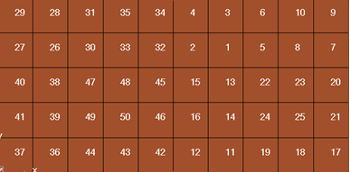
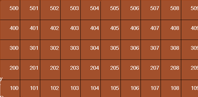
Below is the renumbered mesh. X is the primary axis and we incremented by 1, and Y is the secondary axis and we incremented by 100.
