The Material Orientation tool provides several methods of assigning material x
directions for shell and solid elements, and additionally z directions for solid
elements.
From the menu bar, click Aerospace > Composites > Material Orientation.
Restriction: This tool is applicable for shell element
only.
Select the Entities on which to assign material
orientation, either Elements or Properties.
Set the Color of orientation vectors drawn after applying
material orientation.
To set the scale of orientation vectors drawn after applying material
orientation, set Scaling Option to Auto or Manual.
Type a value into the Size field for the manual input for
size of orientation vectors drawn after applying material orientation.
Set the X direction method. Choose from the following:
Curve – spatially map input curve(s) as the x direction
Lines/Edges – lines which define the orientation
Flip direction – for lines/edges only. Determines whether the
curve provided is +x direction or -x direction.
Nodes – list of lines that define the orientation
System ID – system assigned as orientation
System Axis – system and axis of system to map as x direction
Angle – for OptiStruct and Nastran only. Directly enter rotation applied on
THETA field of element.
Set a value for Normal by choosing one of the
following:
Element Normal – uses element z direction (can be viewed from 2D > composites > element normals panel if elements are selected). Typically, this option
should be used.
Surface Normal – aligns material z direction spatially to selected
surface.
By Curve
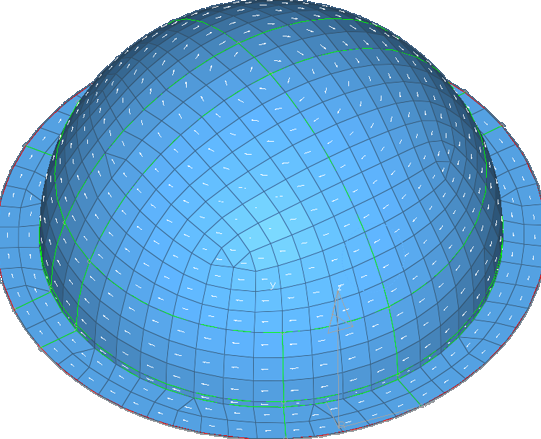
Using curves/lines to create material direction:
Select the elements for which a new material angle will be assigned.
Select the lines or list of nodes to define the material direction. The
element centroid will be taken and projected to the closest line/node
segments and the line tangent direction will be found to assign the material
angle.
Figure 1. A Circular Pattern of the Material Orientation is Assigned Based
on the Outer Circular Line Direction
Other material orientation tools are also available.
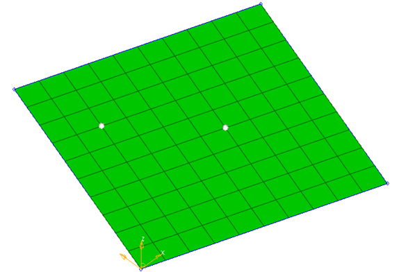
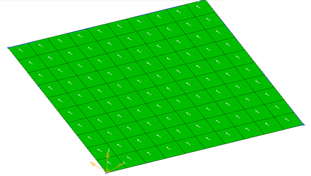
By Node: Element material direction can be assigned using two nodes.
Figure 2. Two Nodes are Selected for Material Direction
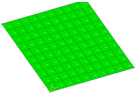
Figure 3. Material Direction in the Same Direction as two Nodes
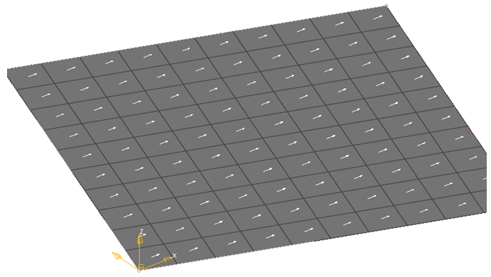
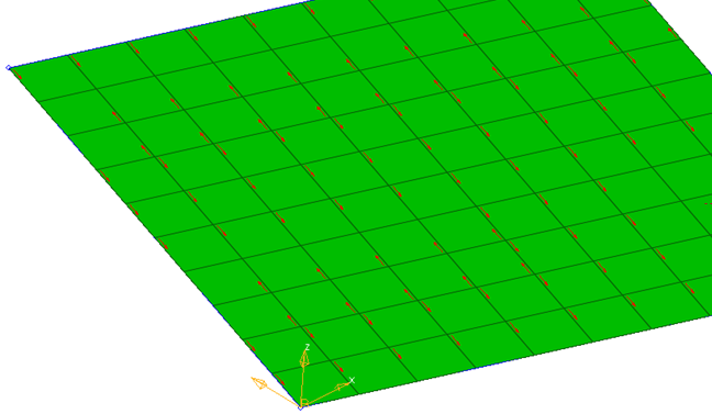
By System ID
The X axis of the selected system is projected to the elements to create element
material direction.
Figure 4. X Axis of the System is used for Projection
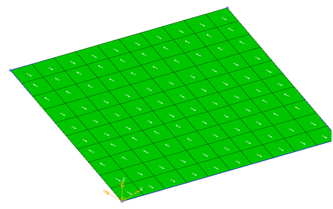
By System Axis
You can select a local system and the direction of the axis to be projected to
elements and create material direction.
Figure 5. System Local Axis 2 is Projected to Create Material System
By Angle
You can provide an angle by which material direction is rotated from the element
N1-N2 direction.
Figure 6. Element N1-N2 Direction
Figure 7. Material System is Created at an Angle to N1/N2 Direction