Create CFD 2D Mesh
Use the CFD 2D Mesh tool to generate hybrid grids containing hexa/penta/tetra elements in the boundary layer and tetra elements in the core or fare field.

CFD 2D Mesh Tool
An overview of the CFD 2D Mesh tool.

Use the CFD 2D Mesh tool to generate hybrid grids containing hexa/penta/tetra elements in the boundary layer and tetra elements in the core or fare field.
- Access
- Go to .
Options
- Element size
- Set the average element size.
- Element type
- Select the type of elements used to create the mesh.
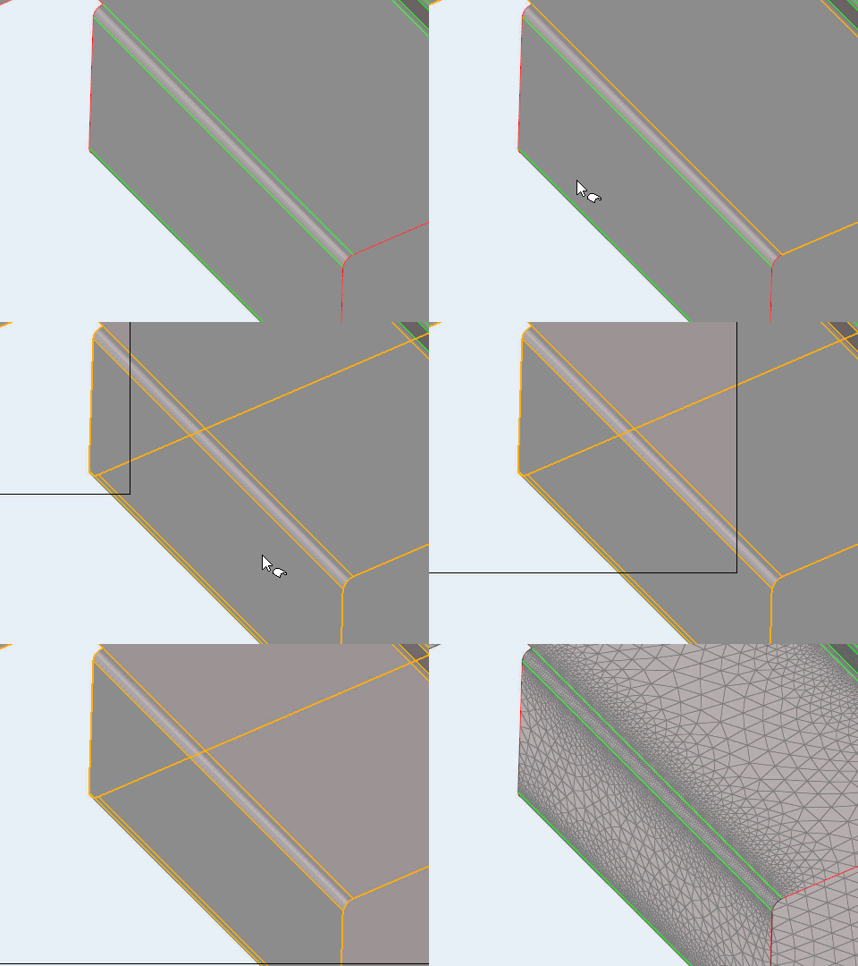
- Curvature based refinement
- Option to turn on mesh refinement based on geometric curvature.
- Method
- Select the adaptive meshing method.
- Minimum size factor
- The minimum element size, as a factor of the average element size. Value must be less than or equal to 1.
- Maximum deviation factor
- The maximum allowable deviation between an element edge and a geometry edge, as a factor of the average element size.
- Feature angle
- The maximum allowable break angle between adjacent elements.
- Growth rate
- The factor to control the rate of transition in case of element size change.
 to define surface mesh options.