Scooter - Trailing Arm - Mono Shock

Model Use
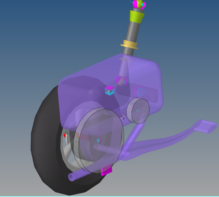
The Rear Monoshock Swing Arm Suspension system can be used in Rear half vehicle or full vehicle models of a two-wheeler. The default geometry and mass approximate that of a two-wheeler scooter, but the model and data can be revised to reflect any size two wheeler.
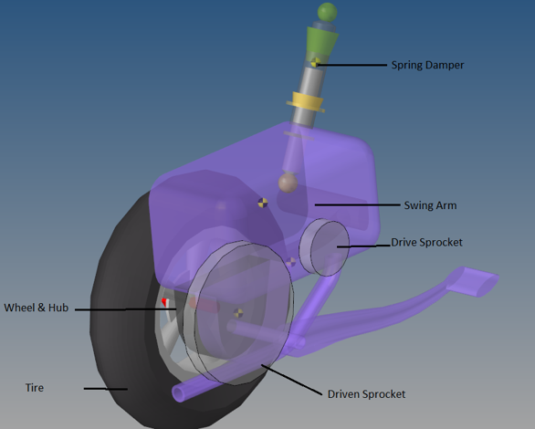
- The wheel body represents the mass and inertia of the tire and the rim.
- The wheel hub body represents the mass and inertia of other rotating bodies such as a brake rotor. The wheel hub and brake rotor have no associated graphics.
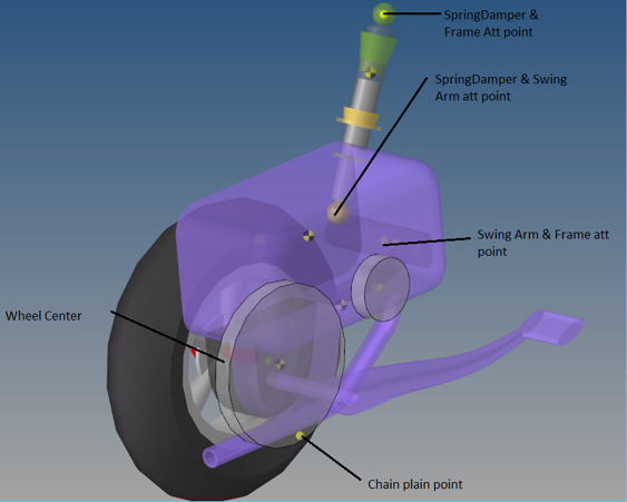
- The wheel and wheel hub parts use the Wheel center location as the center of gravity.
The image below shows the Project browser view of the systems on a fully populated front suspension model. The Rear Monoshock Swing Arm system has six “child” systems.

Points

Bodies

Bushings and Joints
| Label | Type | Body 1 | Body 2 | Point | Notes |
|---|---|---|---|---|---|
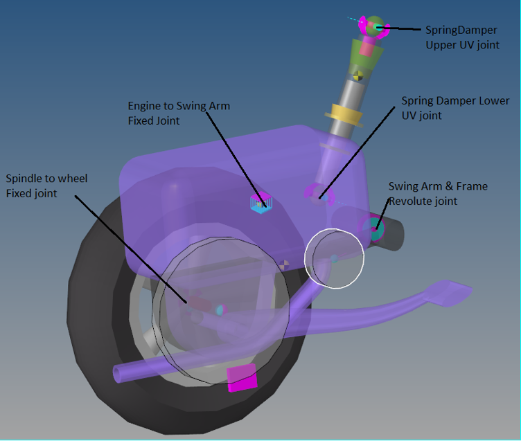
| Frame Swingarm Attachment Joint | Revolute | Swing Arm | Frame | Frame steering Att Point | |
| Swingarm Spindle Att Joint | Fixed | Spindle | Swing Arm | Rear Wheel Center | |
| Spindle to Wheel | Revolute | Rear Wheel | Spindle | Front Wheel Center |
