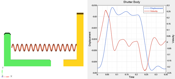
MV-7008: Co-simulation with AcuSolve
In this tutorial, you will learn how to setup a model in MotionView that will be coupled with AcuSolve.
With the addition of a co-simulation interface between MotionSolve and AcuSolve, you can now solve multi-physics problems that involve complex rigid body movement, coupled with fluid flow, that generates pressure forces on the rigid bodies. This capability lets you enhance the fidelity of your multi-body system, letting you generate more realistic results.
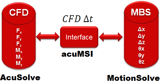
In this scenario, MotionSolve computes the displacements and rotations for the rigid bodies, while AcuSolve computes the forces and moments on those bodies. Both solvers exchange data with each other while stepping forward in time via the TCP socket protocol. This means that the two solvers can be located on different machines and on different platforms and still communicate with one another. For example, the CFD simulation can run on an HPC, while the MBS simulation can run locally on a laptop.
Tutorial Objectives
You will use the MotionSolve-AcuSolve co-simulation interface to couple the rigid body dynamics of a check valve within a pipe with the flow field. The AcuSolve model has already been setup for you and is located at <installation_directory>\tutorials\mv_hv_hg\mbd_modeling\motionsolve\cosimulation\Check_Valve_Coupled.acs. Steps for running this model in AcuSolve are included as part of this tutorial.
To learn more about how to setup the model in AcuSolve, please refer to <installation_directory>\acusolve\<platform>\help\acu\acusolve_tut\Tutorials\Check_Valve_Coupled\.
Software Requirements
| Machine A | Machine B | ||
|---|---|---|---|
| Software | Platform | Software | Platform |
| MotionSolve/MotionView | Windows 64-bit or Linux 64-bit | AcuSolve | Windows 64-bit or Linux 64-bit |
From the table above, the co-simulation is supported for both Windows and Linux platforms (64-bit). Cross platform co-simulation is also possible.
Simulation Environment
- Establishing a connection to both MotionSolve and AcuSolve.
- Communicating the displacements and rotations from MotionSolve to AcuSolve.
- Communicating the forces and moments from AcuSolve to MotionSolve.
- Managing runtime and licensing.
Pipe with a check valve
A check valve is a mechanical device that permits fluid to flow in only one direction. This is controlled by a shutter body. Fluid flowing in one direction pushes the shutter body in one direction, thereby opening the valve. Fluid flowing in the opposite direction pushes the shutter body in the other direction, which causes the valve to shut and prevents flow reversal in the pipe. Check valves are found in pumps, chemical and power plants, dump lines, irrigation sprinklers, hydraulic jacks, for example.
- A pipe with an inlet and outlet for the fluid flow.
- A check valve assembly that consists of a shutter plate attached to a stem.
- A stop mounted on a perforated plate downstream of the shutter body.
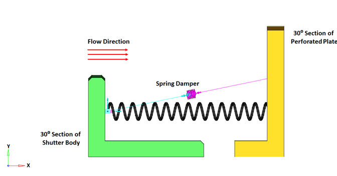
- The fluid flow in the pipe is assumed to be axisymmetric. This allows you to model only a part of the check valve. In this example, a 30 degree section of the geometry is modeled, as shown by the blue part in the figure below. The advantage of doing this is a reduced simulation time while still capturing an accurate solution.
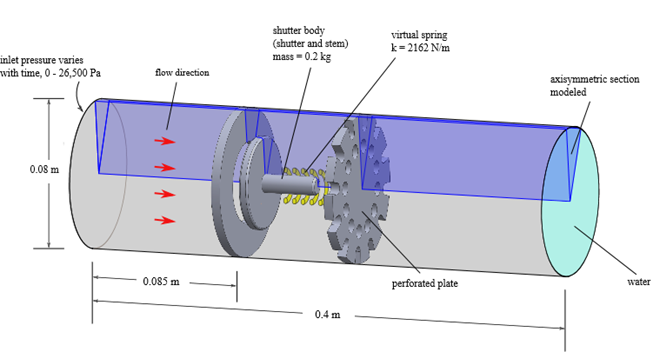
The check valve assembly consists of a disc-like body mounted on a stem. When fluid flows in the direction specified by the red arrows in the figure above, the fluid forces the shutter body to translate in the same direction as the fluid. The motion of the shutter body is also affected by a spring damper attached between the shutter body and the perforated plate. Finally, 3D rigid body contact is modeled between the shutter body and the stop to arrest the motion of the shutter body in the direction of the flow.
For the MBS model, only 1/12 of the shutter body and the perforated plate are modeled.
This dynamics of this kind of model can be termed as being “tightly” coupled between the two solvers. This means that the motion of the rigid bodies affects the fluid flow field, which in turn affects the rigid body motion in a cyclical fashion.
The rest of this tutorial assumes that this model has been correctly setup in AcuSolve. Note that the model is designed to translate the shutter body until it collides with the perforated plate. The MotionView model has been designed with a contact between these two bodies that causes the shutter body to rebound appropriately. To allow the rigid bodies to come into contact without the AcuSolve finite element mesh fully collapsing, the perforated plate in the fluid model has been offset by 0.002m in the positive X direction. This allows the MotionView model to react as specified by the contact entity while keeping the AcuSolve mesh from fully collapsing.
Load the Model in MotionView
Specify the “Wet” Body That Will Interact with AcuSolve
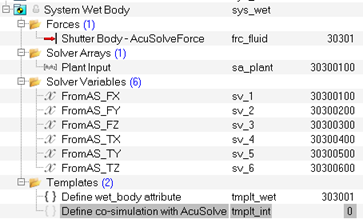
To couple with AcuSolve, you need to specify one or more "wet" bodies. A "wet" body is a body in the MotionSolve model which interacts with the fluid flow and thus has forces and moments acting on it. Such a body can translate or rotate due to the actuating fluid force/moment as computed by AcuSolve as well as due to any actuating forces/moments in the MotionSolve model. In this example, we will define a single "wet" body – the shutter body that translates along the X axis due to fluid impinging on it.
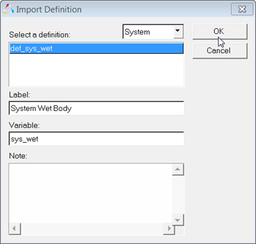
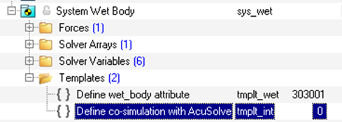
To specify a body as "wet" in MotionView, you have to make use of a system definition, which is described below.
Run the Model without Co-simulating with AcuSolve
To make sure that the MotionView model is setup correctly, run the model in MotionSolve and make sure there are no warning/error messages from MotionSolve.
Verify the Model between MotionSolve and AcuSolve
To successfully run the co-simulation, the model created in MotionView and the model created in AcuSolve must be consistent. The following criteria need to be met in order for the two models to be consistent.
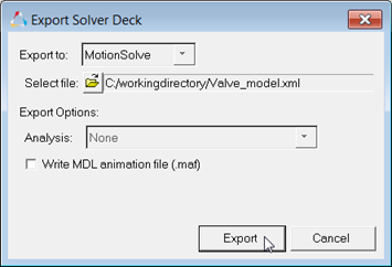
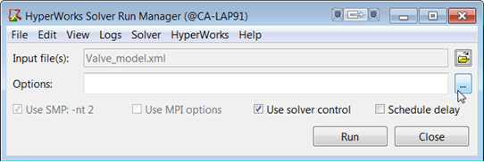
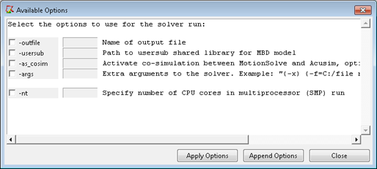
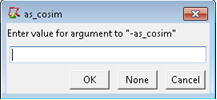
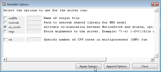
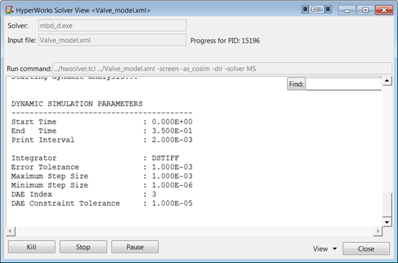
Run the MotionSolve and Middleware Executables for Co-simulation from the MotionSolve Run Manager
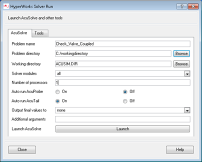
Run the AcuSolve Executable for Co-simulation
Post-process the Results from the Co-simulation
HyperView and HyperGraph can be used to post process the co-simulation results within the HyperWorks Desktop environment.
To launch HyperView (HyperGraph), from the Start menu, select .
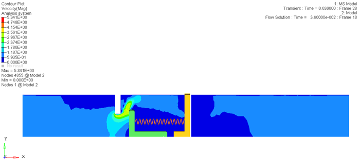
The animation H3D generated by the MotionSolve part of the co-simulation contains only the results from MotionSolve. Similarly, the result files from AcuSolve only contain the results for the AcuSolve model. To animate the results from the co-simulation, follow these steps:
Plotting the MotionSolve Results in HyperGraph
You can also interpret the results with a two dimensional plot using HyperGraph. HyperWorks Desktop can be used in a multi-window layout, allowing both HyperView and HyperGraph to be open at the same time.
