ACU-T: 5000 Centrifugal Air Blower with Moving Reference Frame (Steady)
Prerequisites
Prior to starting this tutorial, you should have already run through the introductory HyperWorks tutorial, ACU-T: 1000 HyperWorks UI Introduction, and have a basic understanding of HyperMesh, AcuSolve, and HyperView. To run this simulation, you will need access to a licensed version of HyperMesh and AcuSolve.
Prior to running through this tutorial, copy HyperMesh_tutorial_inputs.zip from <Altair_installation_directory>\hwcfdsolvers\acusolve\win64\model_files\tutorials\AcuSolve to a local directory. Extract ACU-T5000_BlowerSteady.hm from HyperMesh_tutorial_inputs.zip.
Since the HyperMesh database (.hm file) contains meshed geometry, this tutorial does not include steps related to geometry import and mesh generation.
Problem Description
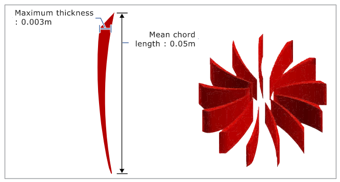
The problem to be addressed in this tutorial is shown schematically in Figure 1 and Figure 2. It consists of a centrifugal blower with a wheel of forward curved blades, and a housing with inlet and outlet ducts. The fluid through the inlet plane enters the hub of the blade wheel, radially accelerates due to centrifugal force as it flows over the blades, and then exits the blower housing through the outlet plane. Because they're relatively cheaper and simpler than axial fans, centrifugal blowers have been widely used in HVAC (heating, ventilating, and air conditioning) systems of buildings.

Open the HyperMesh Model Database
Set the General Simulation Parameters
In this step, you will set the simulation parameters that apply globally to the simulation.
Create a Moving Reference Frame
In this step, you will create a rotating reference frame for the fluid in the impeller region so that the elements in those regions are solved in the given rotating reference frame and rotational body forces are added to that volume set.
Set Up Boundary Conditions and Material Model Parameters
Compute the Solution
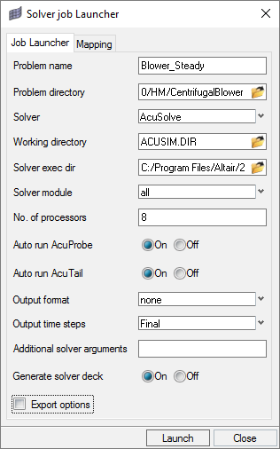
In this step, you will launch AcuSolve directly from HyperMesh and compute the solution.
Run AcuSolve
Post-Process the Results
Create a Pressure-Rise Plot in AcuProbe
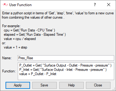
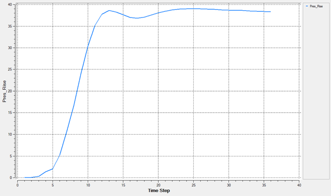
As the solution progresses, the AcuTail and AcuProbe windows are launched automatically. In this step, you will create a User Defined Function (UDF) and generate a plot of the pressure rise between the inlet and outlet.
Open HyperView and Load the Model and Results
Create a Pressure Contour on a Section Cut Plane
Summary
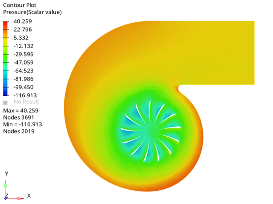
In this tutorial, you successfully learned how to set up a steady state simulation involving a rotating reference frame in a centrifugal blower. You started by importing the mesh and then once the case was set up, you generated a solution using AcuSolve. Then, you computed the pressure rise using AcuProbe and created a contour plot for pressure on a cut plane using HyperView.


