ACU-T: 5300 Ship Hull Static
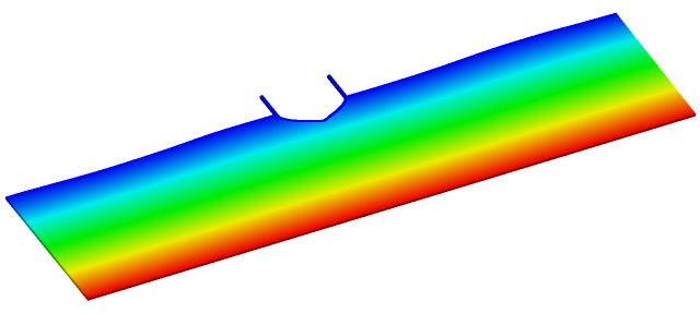
This tutorial provides the instructions for setting up, solving and viewing results for a simulation of flow around a static ship hull. In this simulation, a wave hits the static ship hull and the flow around the ship is simulated. This tutorial is designed to introduce you to a number of modelling concepts necessary to perform Free-Surface simulations.
- Use of a User Defined Function (UDF) for the gravity wave generation
- Mesh extrusions
- Periodic boundary conditions
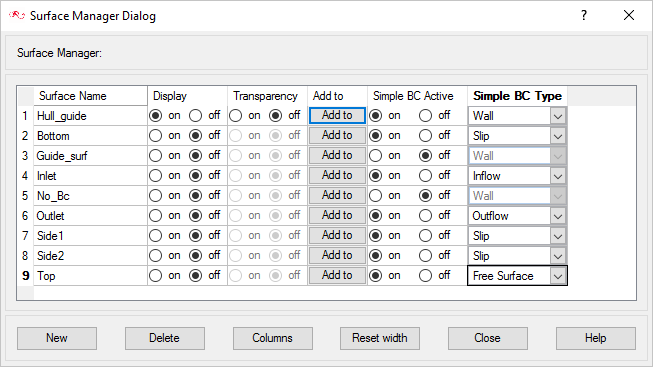
- Use of Surface Manager to apply surface attributes
- Free surface
- Guide surface
- Use of hydrostatic pressure for boundary conditions
- Arbitrary mesh motion using ALE (Arbitrary Lagrangian-Eulerian) method
- Analyze the problem
- Start AcuConsole and create a simulation database
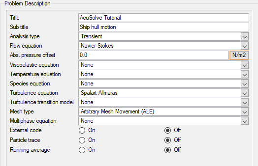
- Set general problem parameters
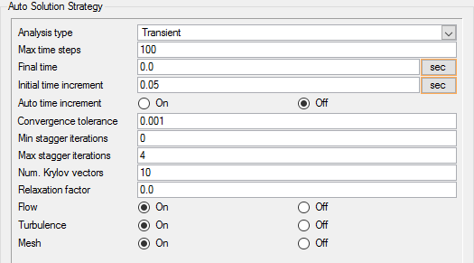
- Set solution strategy parameters
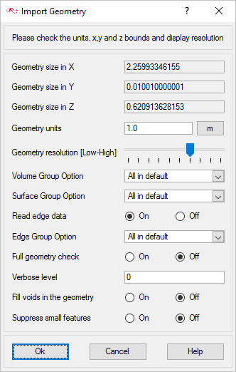
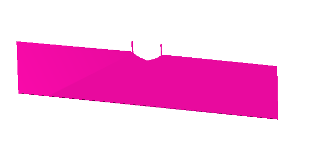
- Import the geometry for the Wigley-hull
- Create a volume group and apply volume parameters
- Create surface groups and apply surface parameters
- Set global meshing parameters
- Set mesh extrusion and periodic boundary conditions
- Generate the mesh
- Run AcuSolve
- Monitor the solution with AcuProbe
- Post-processing the nodal output with AcuFieldView
Prerequisites
You should have already run through the introductory tutorial, ACU-T: 2000 Turbulent Flow in a Mixing Elbow. It is assumed that you have some familiarity with AcuConsole, AcuSolve, and AcuFieldView. You will also need access to a licensed version of AcuSolve.
Prior to running through this tutorial, copy AcuConsole_tutorial_inputs.zip from <Altair_installation_directory>\hwcfdsolvers\acusolve\win64\model_files\tutorials\AcuSolve to a local directory. Extract wigley_hull.x_t and wave.c from AcuConsole_tutorial_inputs.zip.
The color of objects shown in the modeling window in this tutorial and those displayed on your screen may differ. The default color scheme in AcuConsole is "random," in which colors are randomly assigned to groups as they are created. In addition, this tutorial was developed on Windows. If you are running this tutorial on a different operating system, you may notice a slight difference between the images displayed on your screen and the images shown in the tutorial.
Analyze the Problem

Figure 1. Schematic of a Ship Hull
Generation of Surface Gravity Waves

Figure 2. Gravity Waves
Figure 2 depicts parameters that define a simple, progressive gravity wave. This wave can be modeled in the form of the sinusoidal wave profile, shown below.
where
is the horizontal particle velocity of wave
is the speed of the wave
U is the velocity amplitude of disturbance
is wave number =
is the wave length of the wave
is the depth of the water
is the frequency of the wave =
is the time period of the wave
t is the time
In the present simulation we use the following values for the variables of above equation:
U = 0.1256 m/s
= 1.0 sec
= 12.566 m-1
= 0.01 m/s
= 0.5 m
In the present tutorial, at the inlet you will generate the wave for 2 seconds and simulate the motion of the wave for 5 seconds. A UDF (wave.c) written in C language is used for this purpose. For the details of the functions used in the wave.c, refer to the AcuSolve User-Defined Functions Manual.
Two Dimensional Simulations in AcuSolve
AcuSolve does not support a CFD analysis on a 2D surface mesh. However a 2D analysis can be simulated on a volume mesh by having a single element extrusion along the perpendicular direction of 2D surface of interest and then having identical boundary conditions of symmetry or slip on both sides of extrusion. This way you can ensure that the solution does not vary along the thickness (extrusion), which is essentially a 2D representation of the problem. The present tutorial uses this approach.
Define the Simulation Parameters
Start AcuConsole and Create the Simulation Database
In this tutorial, you will begin by creating a database, populating the geometry-independent settings, loading the geometry, creating groups, setting group attributes, adding geometry components to groups, and assigning mesh controls and boundary conditions to the groups. Next you will generate a mesh and run AcuSolve to solve for the number of time steps specified. Finally, you will visualize some characteristics of the results using AcuFieldView.
Set General Simulation Parameters
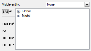
In next steps you will set attributes that apply globally to the simulation. To simplify this task, you will use the BAS filter in the Data Tree Manager. This filter reduces the number of items shown in the Data Tree to make navigation of the entries easier.
The general attributes that you will set for this tutorial are for turbulent flow, transient analysis, and mesh type as arbitrary mesh movement (ALE).
Set Solution Strategy Attributes
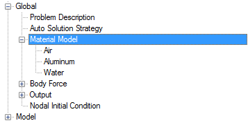
Set Material Model Parameters
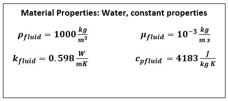
Figure 6.
Import the Geometry and Define the Model
Import the Geometry
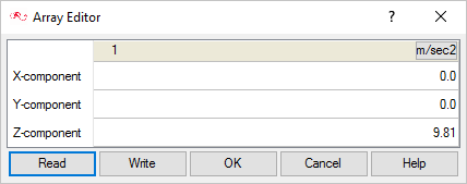
Set Body Force
Apply Volume Attributes
When the geometry was imported into AcuConsole, all volumes were placed into the "default" volume container.
In the next steps you will rename the default volume group container, set the material for that group and set mesh motion for the fluid volume.
When the geometry was loaded into AcuConsole, all geometry volumes were placed in the default volume group container. In the previous steps, you selected a geometry volume to be added to Guide_Vol_Ship container that you created. At this point, all that is left in the default volume group is the fluid volume. Rather than create a new container, add the fluid volume in the geometry to it, and then delete the default volume container, you can rename the container and modify the attributes for this group.
Create Surface Groups and Apply Surface Parameters
Surface groups are containers used for storing information about a surface, including solution and meshing parameters, and the corresponding surface in the geometry that the parameters will apply to.
In the next steps you will define surface groups, assign the appropriate settings for the different characteristics of the problem, and add surfaces to the group containers.
In the process of setting up a simulation, you need to move into different panels for setting up the boundary conditions, mesh parameters, and so on, which can sometimes be cumbersome, especially for models with too many surfaces. To make it easier, less error prone, and to save time, two new dialogs are provided in AcuConsole. Use the Volume Manager and Surface Manager to verify and provide the information for all surface or volume entities at once. In this section some features of Surface Manager are exploited.
Side1 and Side2
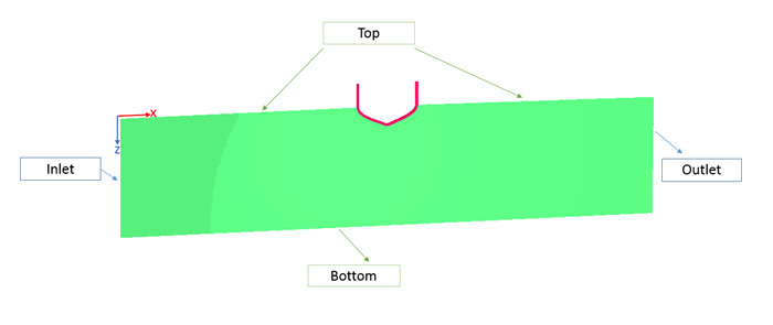
The present simulation is a 2D representation of a ship in water. Hence it is appropriate to set the Side1 and Side2 with the slip boundary condition to simulate that effect.
- In the Data Tree, expand Side1.
- Double-click Simple Boundary Condition to open the Simple Boundary Condition detail panel.
- Check that the Type is Slip.
- Change the Mesh displacement BC type to Slip.
- Repeat the settings for the surface Side2.
AcuConsole has a special feature named Propagate that can speed up the process of simulation setup and save time. This feature copies the attributes (it may be Simple Boundary Condition, Surface Output, Surface Mesh Attributes, Element Set, Volume Mesh Attributes, and so on) set for one surface set or volume set to another surface set or volume set. For example, in a simulation model if there are 10 surface sets with simple boundary condition set to Slip, then you can use this feature. You need to manually set the boundary condition for one surface and use the Propagate feature for all other surfaces.
- Under Side1, right-click Simple Boundary Condition and select Propagate.
- Select the surface Side2 and click Propagate.
Top
Bottom
Outlet
During the simulation there will be certain time points (particularly when trough is formed at the outlet surface) at which the flow enters the domain through certain portion of outlet surface, which is called back flow. Back flow may lead to instability temperature, turbulence variables. Enabling Back flow conditions allows nodal boundary conditions to be specified for these variables only on nodes where there is flow re-entering the domain. Assuming the outlet is sufficiently far away from ship hull, eddy viscosity value can set as that of the Inlet, for example, 1e-05
No_Bc
The No_Bc surface set contains the surfaces of Guide_Vol_Ship which do not participate in actual simulation. Hence it is appropriate to disable the Boundary condition for this surface.
- In the Data Tree, expand No_Bc.
- Uncheck the Simple Boundary Condition check box.
Guide_surf
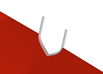
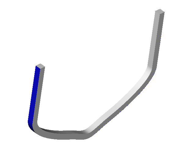
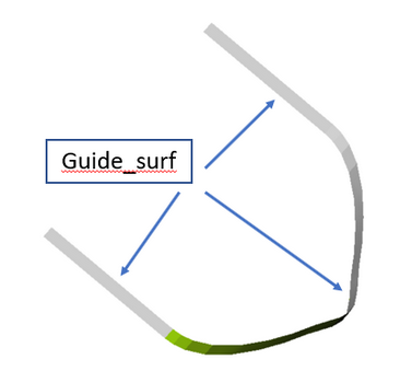
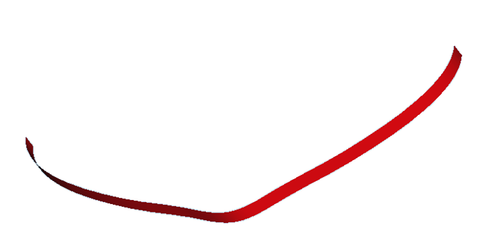
This surface belonging to the Guide_Vol_Ship will remain stationary in the present simulation and provide as a guide for the fluid around. Hence we define it as Guide Surface with no mesh motion.
Hull_guide
Inlet
At the Inlet, you will provide the horizontal velocity of the gravity waves given by Equation 1. This boundary condition at the inlet will be defined using Nodal Boundary conditions with UDF.
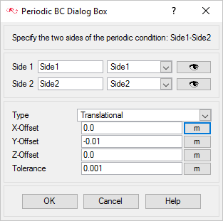
Define the Periodic Boundaries
Check Periodic Boundary Conditions
The following steps define the periodic boundary conditions for various variables for Side1 and Side2.
Set Nodal Output Frequency
The Nodal Output Frequency determines at what frequency or time interval the solution results would be stored to be used for post processing within AcuFieldView.
Compile the UDF
A UDF in the form of C language (wave.c) is provided with the tutorial. This C program should be compiled using the following steps.
-
To compile the UDF on Windows:
- Start AcuConsole Command Prompt from the Windows Start menu by clicking .
- Use the cd command to change the directory to the current working directory.
- Enter the command acuMakeDll –src wave.c.
-
To compile the UDF on Linux:
- In the terminal, use the cd command to change the directory to the current working directory.
- Enter the command acuMakeLib -src wave.c.
Assign Mesh Controls
Set Global Mesh Parameters
Now that the simulation characteristics have been set for the whole problem, the next step is to generate the mesh.
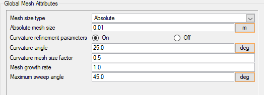
Global mesh attributes are the meshing parameters applied to the model as a whole without reference to a specific geometric volume, surface, edge, or point. Local mesh attributes are used to create mesh generation controls for specific geometry components of the model.
In the next steps you will set the global mesh attributes.
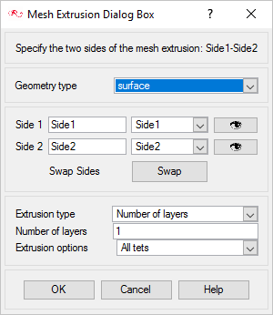
Define Mesh Extrusion
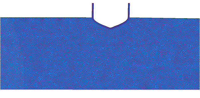
The present simulation is equivalent to a 2D representation of the model. In AcuSolve, 2D models are simulated by having just one element across the thickness. In this case, there has to be only one element between Side1 and Side2. This can achieved with mesh extrusion process. Since you are using identical boundary conditions on Side1 and Side2, using one element between them will ensure that there is no variation in nodal values across thickness and hence ensuring the simulation of a 2D model. In the following steps you will define the process of extrusion of the mesh from Side1 to Side2.
Generate the Mesh
In the next steps you will generate the mesh that will be used when computing a solution for the problem.
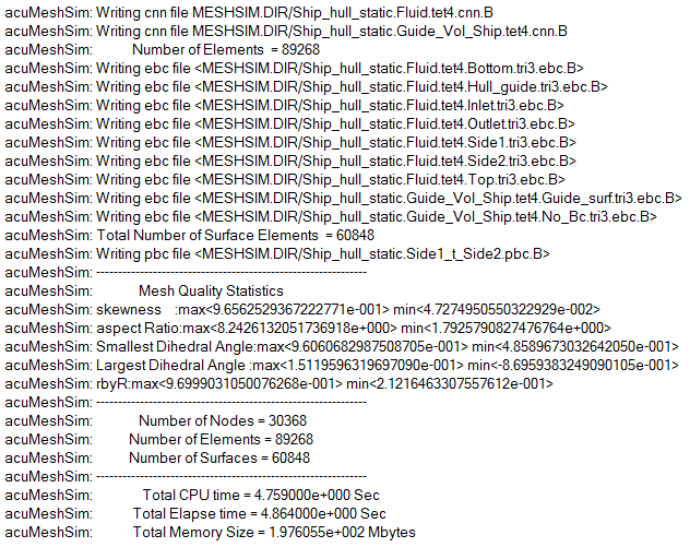
Split Nodes
At this point, the Hull_guide surface has all nodes that are attached to Fluid. A duplicate set of nodes has to be created, so that one set of the nodes follow the Fluid motion and another set stays attached to the surface Guide_surf. The following steps illustrate the process of splitting the nodes.
Compute the Solution and Review the Results
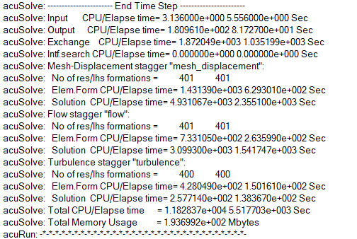
Run AcuSolve
In the next steps you will launch AcuSolve to compute the solution for this case.
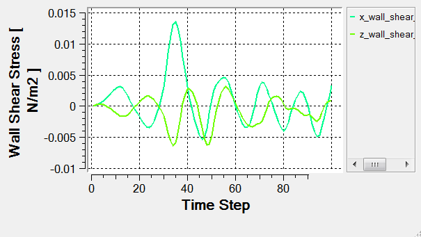
Monitor the Solution with AcuProbe
AcuProbe can be used to monitor various variables over solution time. In the present simulation it is worthwhile to monitor the forces on the ship hull.
View Results with AcuFieldView
Now that a solution has been calculated, you are ready to view the flow field using AcuFieldView. AcuFieldView is a third-party post-processing tool that is tightly integrated to AcuSolve. AcuFieldView can be started directly from AcuConsole, or it can be started from the Start menu, or from a command line. In this tutorial you will start AcuFieldView from AcuConsole after the solution is calculated by AcuSolve.
In the following steps you will start AcuFieldView and create an animation of the ship hull motion with the contours of z-mesh displacement.
Start AcuFieldView
View Water Displacement Around the Ship
These steps are provided with the assumption that you are able to manipulate the view in AcuFieldView to have a white background, perspective turned off, outlines turned off, and the viewing direction set to +z. If you are unfamiliar with basic AcuFieldView operations, refer to Manipulate the Model View in AcuFieldView.
Summary
- User Defined Function (UDF) for surface gravity wave generation
- Mesh extrusions and periodic boundary conditions
- ALE based mesh motion approach
- Use of the Surface Manager to apply surface attributes
- Use of hydrostatic pressure as a boundary condition
- Free surface and Guide surface capabilities in AcuSolve
