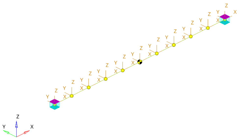
MV-1027: Model a Point-to-Deformable-Curve (PTdCV) Higher-Pair Constraint
In this tutorial, you will learn how to model a PTdCV joint (point-to-deformatble-curve) joint.
Create Points
In this step you will create the points for the PTdCV model.
Create Bodies
In this step you will create the bodies for the PTdCV model.
Create Markers
In this step you will define the markers required for the beam.
Create Joints
In this step you will define the fixed joints necessary for the model.
-
Open the Add Joint or JointPair dialog in one of the
following ways:
- From the Project Browser, right-click on Model and select .
- On the Model-Constraints toolbar, click the
 (Joints) icon.
- In the dialog, for Label enter Joint0.
- In the drop-down-menu, select Fixed Joint and click OK.
-
In the panel, double-click
 .
.
- In the dialog, choose Beam and click OK.
-
Double-click
 .
.
- In the dialog, select Ground Body and click OK.
-
Double-click
 .
.
- In the dialog, select PointbeamInterface1 and click OK.
-
Repeat steps 1
through 9 to
create a second fixed joint.
- For Label, enter Joint1.
-
For
 , choose
PointbeamInterface2.
- For all other steps, use the same inputs as you did for Joint0.
Create Deformable Curves
In this step you will define a deformable curve on the surface of the beam.
-
Open the Add DeformableCurve dialog by doing one of the
following:
- From the Project Browser, right-click on Model and select .
- On the Model-Reference toolbar, click the
 (Deformable Curve)
icon.
- In the dialog, for Label enter DeformableCurve0.
- Click OK.
-
In the Properties tab, specify the properties of the deformable curve.
Create the PTdCV Joint
In this step you will create the advanced PTdCV joint.
Create Graphics
In this step, you will create a graphic for the ball.
-
Open the Add Graphics or GraphicPair dialog in one of the
following ways:
- From the Project Browser, right-click on Model and select .
- On the Model-Reference toolbar, click the
 (Graphics) icon.
- In the dialog, for Label enter Graphic0.
- In the Type drop-down menu, choose Sphere. Then click OK.
-
In the Connectivity tab, double-click
 .
.
- In the dialog, select Ball and click OK.
-
Double-click on
 .
.
- In the dialog, select Point4 and click OK.
- In the Properties tab, under Radius enter 2.0.
- In the Visualization tab, choose a color for the graphic.
Find Nodes
In this step, you will return to the Bodies Panel and find the Nodes on the beam.
Run the Model
In this step you will run the model with the PTdCV joint constraint.
View the Results
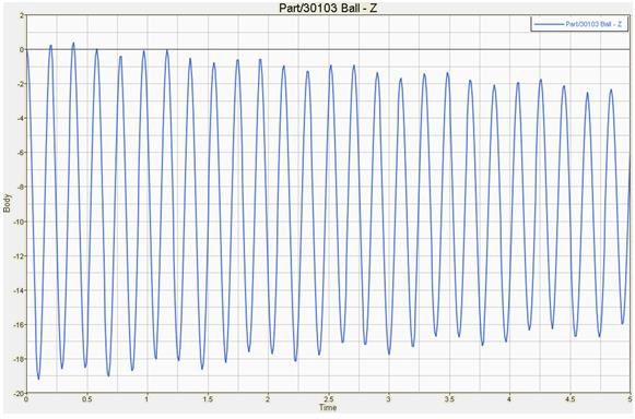
In this step, you will plot the Z position of the center of mass of the ball.


