Spotweld
Spot Weld checks identify problems with spot welds in the model and shows them in the report.
The identified problems in spot welds are highlighted using a cross-hair in the images.
-
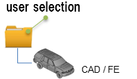
Click the folder icon and navigate to the model to import (Folder/File
selections).
The folder or the selected location must contain the spot weld file. The spot weld file type must be set in the config file.Figure 1.
-
Click View Report to display the Summary PowerPoint
report.
Figure 2. PowerPoint Summary . (Stored in Report Path)
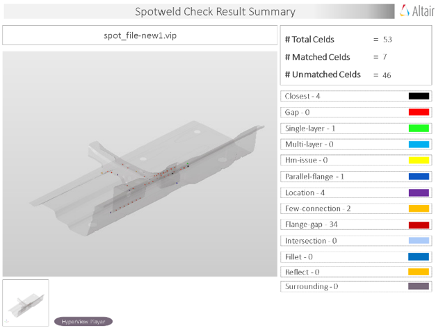 Figure 3. PowerPoint Detailed Report. (Stored in Report Path)
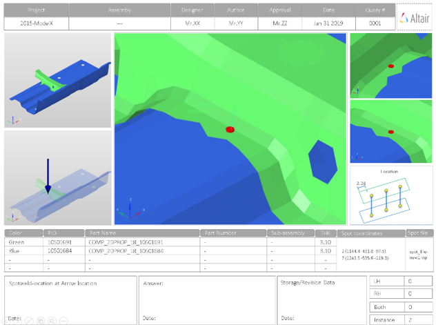
Output
Overview of the PowerPoint report generated from the Spot Weld check.
A PowerPoint report is separated into several sections.
- Report Header
- Project name, assembly name, and slide number.
- Assembly Picture
- Image of the components that have spot weld issues.
- H3D Image
- Section can be viewed in the HyperView Player, and shows an H3D image shows the FE model with the spot weld marked with Cross Hairs.
- Issue Details
- Details of components which have spot weld issues.
- User Review Section
- Used to add additional information when exchanging information with designers/engineers.
- Additional Info
- Occurrences of the issue shown in the current slide. The number of instances show the number of occurrences of the issue.
Supported Spotweld Checks
Overview of the spotweld checks available to perform in the model.
- Closest
- Detects the spot welds which are too close to each other. The closeness
tolerance is used as the criteria for deciding if two spot welds are
considered as too close.Figure 4.
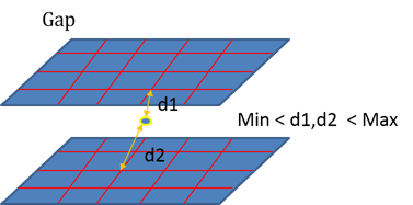
- Gap
- Detects the spot welds in which the distance between the spot weld
location and the connected components lie outside the given maximum and
minimum gap limits.Figure 5.
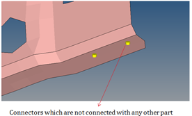
- Single Layer
- Detects the spot welds which are connected to only one part. The second
part is missing from the spot weld definition.Figure 6.
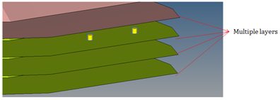
- Multiple Layers
- Detects the spot welds which are connected to more parts than what is
specified as the threshold number for multiple parts.Figure 7.
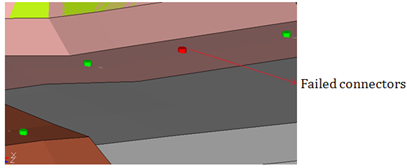
- HyperWorks Issues
- Detects the spot welds that failed during realization.Figure 8.
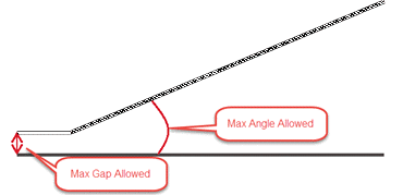
- Non-Parallel Flanges
- Detects the spot welds that are connecting the non-parallel flanges.
Flanges are said to be non-parallel if there is a gap or step of the
flanges diverge.Figure 9.
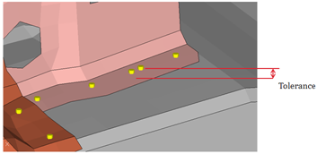
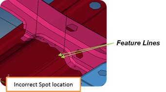
- Incorrect Location
- The Model Verifications creates feature lines internally to check the
distance between the connector and the feature line. When the distance
between the connector and feature line is less that the specified
tolerance, the location of the connector is said to be incorrect. The
feature angle used to create feature lines is specified in the Feature
Angle field.Figure 10.
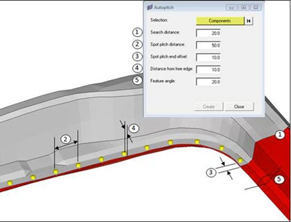
- Few Connections
- Detects the possible locations where the spot welds may be missing. This
detection is done based on the adjacent spot welds in that area.Figure 11.
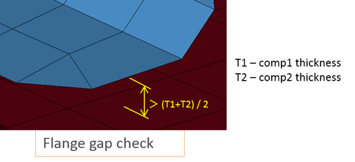
- Flange Gap
- Detects if the gap between the flanges is within the minimum and maximum
limit of the average of the component thicknesses being connected by the
weld.Figure 12.
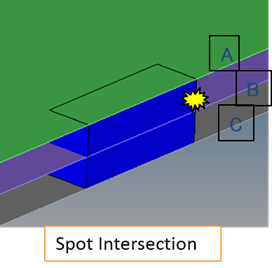
- Spotweld Intersection
- Detects if a spot weld has an intersection with an unconnected
component.Figure 13.
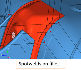
- Spotweld on Fillet
- Detects if any spot weld is located on fillet features.Figure 14.
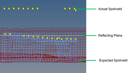
- Reflect Spotweld
- Detects if any spot weld can be realized on reflecting its location
about a plane defined by you.Figure 15.