Shape Optimization
An optimization method wherein the outer boundary of the structure is modified to solve the optimization problem.
Using finite element models, the shape is defined by the grid point locations and shape optimization modifies these locations to update the shape.
Shape variables are required to implement shape optimization. Each shape variable is defined by using a DESVAR Bulk Data Entry. If a discrete design variable is desired, a DDVAL Bulk Data Entry needs to be referenced for the design variable values. DVGRID Bulk Data Entries define how much a particular grid point location is changed by the design variable. Any number of DVGRID Bulk Data Entries can be added to the model. Each DVGRID Bulk Data Entry must reference an existing DESVAR Bulk Data Entry if it is to be a part of the optimization. The DVGRID data in OptiStruct contains grid location perturbations, not basis shapes.
The OUTPUT, DVGRID option creates shape variable definitions for displacement or eigenvector results of linear static, normal modes, or linear buckling analyses. These shape variable definitions can then be used in subsequent optimizations. This process facilitates the use of "natural" shape functions.
The generation of the design variables and of the DVGRID Bulk Data Entries is facilitated by the HyperMorph utility, which is part of the HyperMesh software.
Shape optimization is typically applicable for both small and large shape changes. Small shape change implies that the connectivity between parts in the design space are not updated iteratively.
Large Shape Change Optimization
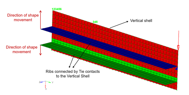
Large shape changes in the contact or connector element interfaces during shape optimization are supported.
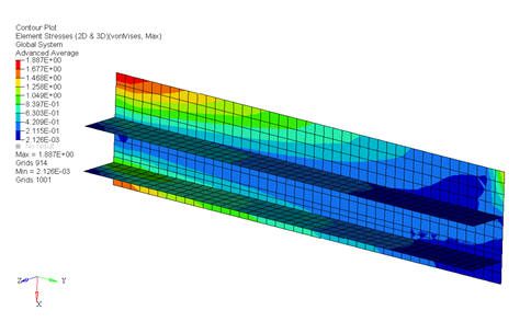
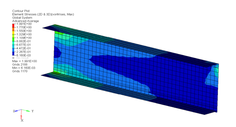
Large shape change optimization is a type of shape optimization which requires updating the location of connector elements or contacts in the model during each iteration of the optimization process. In case of contact, the shape changes of the slave and master surfaces are updated in each iteration.


Currently, large shape change with contact is supported only for node-to-surface type of contact and for connector elements such as CGAP, CGAPG, CWELD and CFAST.
Large shape change will not be turned on, if surface-to-surface type of contact is present in input file regardless of whether such contact is on design region or not. In this case, regular shape optimization is used, where the update of connectivity is not performed during the shape optimization process.
Large shape change optimization is supported for Linear Static, Normal Modes, Buckling Analysis, Response Spectrum Analysis, Frequency Response Analysis and Pure Steady-State Thermal Analysis (only for CGAPG elements and N2S contacts).
If large shape changes are expected for CWELD, CFAST, or CSEAM elements, it is recommended that the connection of surface patch to surface patch is defined using shell property ID’s on sides A and B.
| Mass | Volume | Center of Gravity |
| Moment of Inertia | Static Compliance | Static Displacement |
| Natural Frequency | Buckling Factor | Static Stress, Strain, Forces |
| Static Composite Stress, Strain, Failure Index | Frequency Response Displacement, Velocity, Acceleration | Frequency Response Stress, Strain, Forces |
| Weighted Compliance | Weighted Frequency | Combined Compliance Index |
| Function | Temperature |