Perform automatic checks on CAD models, and identify potential issues with geometry that may slow down the meshing
process using the Verification and Comparison tools.
Many essential utility tools using HyperWorks-Tcl have been developed over the years to support Aerospace customers. A few tools have been collected and upgraded to
be compatible with this release.
Many essential utility tools using HyperWorks-Tcl have been developed over the years to support Aerospace customers. A few tools have been collected and upgraded to
be compatible with this release.
Create linear gaps between corresponding pairs of nodes from one plate to another
plate along the axis of a local coordinate system.
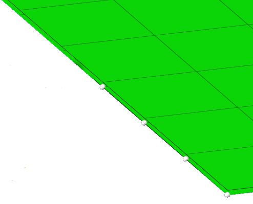
Figure 1.
From the menu bar, click Aerospace > Connections > Linear Gaps.
Select the Dependent Nodes from the first plate.
Select the Independent Nodes from the second
plate.
Assign the correct Tolerance, which is slightly bigger
than the gap.
Select the degree of freedom (DOF) for the MPC (1, 2, 3, 4, 5, or 6).
Click Apply.
A Nastran linear gap is created that
consists of MPC, SPC, SPOINTS and SUPPORT. For example, the following cards are
created.
SPOINT 55 155 (two spoints 55, 155)
SUPPORT 55 0 (support
at one spoint)
SPC 101106 155 0 .05 (spc at the other spoint with
initial gap of 0.05, with DOF=0)
$ SID G1 C1 A1 G2 C2 A2 (MPC for
linear gap. In DOF = 2 for Nastran)
MPC
101106 3 2 1.0 2 2 -1.0
$ G3 C3 A3 G4 C4 A4
55 0 1.0 155 0
-1.0
Note: You can also use this tool to convert other types of 1D
connector elements, such as CGAP, CBUSH, CELAS, to linear gap (MPC/SUPORT,
SPC, SPOINT).
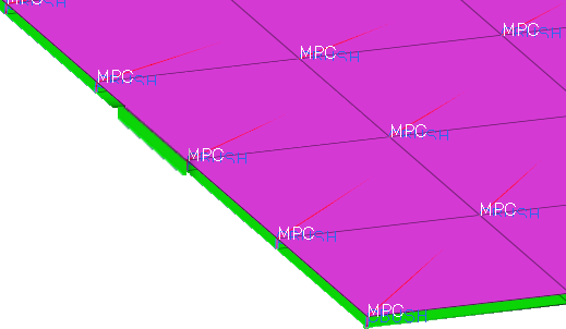
 Figure 2.