Offset on Plates

The Adjust to shell tool can automatically offset a beam element.

A bar2 element can be connected to either a single element's edge or can be shared between two elements at a plate T-junction. The Adjust to shell tool will consider a shell's thickness and offset during offset calculations. In the event of a sharp angle or T-junction, you can position the beam in four different quadrants.

While performing an offset, you can choose whether the adjustment is done on both normal and lateral directions. A normal offset means that the offset is along the element's Y axis, while a lateral offset is along the element's Z axis. In the case of a free edge or T-junction, the beam is adjusted such that its bounding box matches with the edge.


Figure 1.

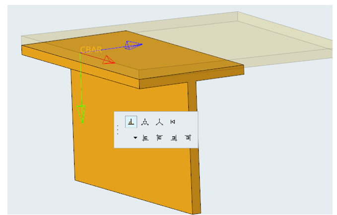
Similar to the Orient context, options determine which shells are considered during the adjustment. They also handle thickness variations between adjacent plates. If the Thickness method option is not set to Averaged, the shell with the minimum (resp. maximum) thickness is used as a reference and adjustments are performed on this shell element.

  1. Select the element in the model that you want to offset.
    A microdialog displays with the Adjust to shell tool highlighted, as shown in the image above.
  2. Choose the direction of adjustment by clicking the down arrow. This can be either Normal and Lateral, Normal, or Lateral.
    Note: The icons will change to reflect these options.
  3. Click the appropriate adjustment tool from the following:
    • Positive base and adjacent
    • Negative base and positive adjacent
    • Positive base and negative adjacent
    • Negative base and adjacent
  4. Select the appropriate element in the model.
    The adjustment is performed on this shell element.
  5. Set options according to the following:
    Option Description
    Offset at Offset at start and/or end.
    Normal from shells Controls which shells are referenced to extract thickness and offset during beam offset.
    Thickness method Controls which thickness is considered when shells adjacent to a node have different thicknesses.
  6. If you need to reset the offset, press the Reset offset button on the far-right of the microdialog.


    Figure 2.
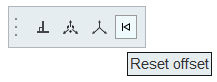
    Note: This is not an Undo operation. Reset will always set to 0,0,0 regardless of previous value.