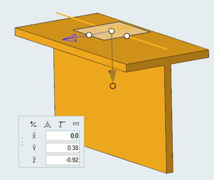
Provide an arbitrary orientation vector in space using the Vector tool.
By selecting an element, the Vector tool can be placed on it and align with the
current orientation vector. The X, Y, and Z components can be edited for precise
orientation. Options available in the tool allows you to flip the orientation vector
or align the vector normal to screen.
Figure 1.
Select the appropriate element in the model.
The microdialog displays.
On the microdialog, click the Use direction
tool to orient button.
The Direction tool displays, as shown in the image above.
Type in the X, Y, and
Z values necessary to orient the tool vector.
Press Enter to accept the values and change the
orientation vector.
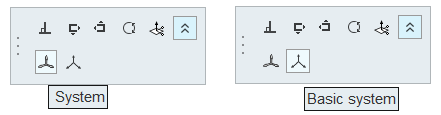
To select in which system the orientation vector component is resolved, click
the ( ) button back in the main microdialog.
The System and Basic System buttons are displayed.
Figure 2.
To resolve components, do one of the following:
Click System. This selects a user-defined system
ID.
Click Basic System. This places all X, Y, and Z
components in the output system of beam node A.
 ) button back in the main microdialog.
The System and Basic System buttons are displayed.Figure 2.
) button back in the main microdialog.
The System and Basic System buttons are displayed.Figure 2.