Altair SimLab 2020.1 Release Notes
Supported CAD
- ACIS (Up to 2019.1.0)
- AutoCAD (Up to 2019)
- CATIA (Up to CATIA V5 R29)
- Creo (Up to 6.0)
- ECAD
- Inventor (Up to 2019)
- JT
- NX (Up to NX 1899)
- Parasolid (32.0.152)
- SOLIDWORKS (Up to 2019)
- STEP
System
- New Features
-
- Home > Move
-
- The following are the support added to the move
tool:
- Snap: To move the selected face to snap input (snap input: face, edge, vertex, node). This is supported for both FEM and CAD (Parasolid) imported with “Save geometry”.
- Fill: To create a separate body between the selected face and snap input. This is supported only for CAD (Parasolid) imported with “Save geometry”.
- The reposition mode in the move tool is simplified for ease of use.
- Support is added to reposition the axis of the move tool/body using the axis marker.
- The following are the support added to the move
tool:
- Home > Move > Transform
- Support added to take a copy of input Parasolid bodies for
the following options:
- Translate
- Rotate
- Mirror
- File > Preferences > Application
-
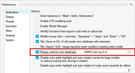
- Added a toggle “Display units for new database” to
set the selected unit system for the new
database.Figure 1.
- Added a toggle to disable the highlighting of
entities and auto-rotation centers based on
user-defined node count limit.
- In an earlier version of SimLab, if the node count exceeds 1M it will automatically disable the entity highlight and rotation center.
-
Note: The performance of entity picking and rotation of large models will be fast by turning on this toggle.
- Added a toggle “Display units for new database” to
set the selected unit system for the new
database.
- Enhancements
-
- File > Preferences > Display
-
- True color settings are made as default. Also, the face edge color will be displayed in black color with thick edges.
- Back side in darker shade toggle will be tuned OFF automatically while tuning ON the true color.
- Mesh control colors are enhanced to display in true color.
- File > Preferences > Mesh
- Support added to mesh identical bodies as instances when "Find identical bodies and mesh as instances" toggle is enabled.
- Resolved Issues
-
- Home > Move > Transform
- Mirroring the pyramid elements results in negative volume elements. This issue is fixed.
Import
- CAD Import
-
- New Features
- JT
- Support added to import materials from the JT file.
- The material name will be read and created with default values. Then, the material will be assigned to the corresponding bodies.
- Improved the performance for facet import for large models. Now, the full car model can be imported in ~2.5 hours.
- Enhancements
- Parasolid
- Option “Add to existing model” is added in Parasolid
import.
- During Parasolid import, if we select more than one Parasolid model and if we turn ON the “Add to existing model” toggle then it will import all the Parasolid model into a single model.
- If the Parasolid model is already present in the database and if we need to import another Parasolid model and add to the existing one, need to turn ON “Add to existing model” toggle.
- Support added to copy (Ctrl+C) and paste (Ctrl+V)
Parasolid bodies imported with “Save geometry in
database” option.
- CAD bodies are copied as instances and connected CAD bodies will be copied as new body.
- Option “Add to existing model” is added in Parasolid
import.
- Result Import
-
- Resolved Issues
- UFX Results import
- Application crashes when saving the model after importing the results using new results reader. Fixed this issue
Graphics and Visualization
- New Features
-
- UI Right Click > Enable Group Display
- Added an option “Enable Group Display” in UI right click to turn ON the group display mode. This will highlight the groups for the visible bodies in group color.
- Body Right Click > Select > Overlapping CAD faces
- Support added to select matching faces between CAD bodies.
- Body Right Click > Move to Sub Model
- Option added to create a sub model and move the selected body into the created sub model.
- Body > Right Click> Select > Associated Groups
- Added an option “Select Associated Groups” in body right click to select the groups associated with selected bodies.
- Face Right Click > Delete
- Support added to delete the faces of a Parasolid model imported with “Save geometry in database” option.
- Body / Face Right Click > Select Features > Slots
-
- Support added to identify slot edges from CAD/FEM bodies.
- Adjacent faces of the slot should be planar.
- Body / Face Right Click > Select Features > Sharp Edges
- Support added to identify sharp edges (both Concave & Convex edges) based on the angle between the two connecting faces.
- Bottom toolbar > View
-
- Support added to rotate the model up, down, left, right, clockwise, counterclockwise and icons are assigned for each rotation method.
- Default Shortcut keys are assigned to each rotation
type as follows:
- Up arrow for Up,
- Down arrow for Down,
- Left arrow for Left,
- Right arrow for Right,
- Left arrow + Ctrl for counterclockwise,
- Right arrow + Ctrl for clockwise rotations respectively.
- Enhancements
-
- Layout Selection
- While opening SimLab, it will pop up a message about the new ribbon layout. To use the layout as in earlier version, select SimLab in View > Applications.
- Color Palette
- The color palette theme is changed from “Default” to “Rainbow”.
- UI Right Click > Reset Model
- Enhanced reset model option to display the model in isometric view.
- Entity > Right Click
-
- The Right click options are rearranged when an entity is selected.
- Grouped all the selection-based options in UI right click for ease of access.
- Failure Mode Right Click
- In quality check failure mode, removed the unwanted option in the right click.
- Group Mode Right Click
-
- Redisplay body – Body belongs to the displayed group entities will be in gray color
- Display body as transparent – Body belongs to the displayed group entities will be in transparent mode
- Display group entities only – Display only the entities of enabled groups in group browser
- Disable group display – Option to disable the groups display
- Display all bodies – To display all the bodies from model browser
- Body Right Click > Unmerge
- Support added to unmerge the bodies by selecting multiple bodies.
- Body Right Click > Select > Associated Entities
-
- Support added to select connected RBE’s from input bodies.
- Support added to get “Center node” and “Dependent nodes” from selected RBE Bodies.
- For RBE bodies, the 2D elements option is supported to get associated 2D elements.
- It will highlight the group entities in UI with selected body in gray color.
- Nodes Right Click> Select > Associated Entities
- Enhanced the tool to ignore the following input nodes while
selecting the associated entities:
- Solid nodes
- RBE center nodes
- Bottom toolbar > Enable Cutting Plane
- True color is extended to cut layers when cutting plane is enabled.
- Cutting Plane Right Click > Cutting Plane Options
-
- Added support to show the bounding edges of the bodies when enable the cutting plane with cut layer display option.
- “Selected bodies” option with “Default view” mode in the Cutting plane options is supported for Parasolid models.
- Database > Right Click > Duplicate Database
- Option added to duplicate the database. The duplicated database will be saved in temp folder.
- Define Axis > Axis marker
- Improved axis marker drawing to display the axis direction clearly.
- Selection Filter > Cylinder
-
- Enhanced cylinder selection filter to work for both cylinder and cone faces.
- Supported for both CAD and FEM faces.
- Inspect > Mass properties
- Supported the computation of mass properties for CAD bodies & point mass.
- Resolved Issues
-
- Body / Face Right Click > Select > Faces by plane
- Face input is not considered for identifying the face using a plane. This is fixed.
- Body / Face Right Click > Select Features
-
- Cones with tiny edge were not identified as full cone when the Parasolid model is imported with “Save Geometry in Database”. This issue is fixed.
- Full cylinders were identified under fillet option. This improper identification is now fixed.
- In few cases, arc edges were not identified properly, which is now fixed.
- Body / Face Right Click > Invert Transparency
- Fix has been made to restrict the picking of FEM entities such as nodes, elements, and element edges when the bodies/faces are in transparent mode.
- Selection Filter > Cylinder
- When the selection filter is set to face filter and pressing the shortcut key “C” twice, instead of retaining in Cylinder filter, reset the selection filter to face filter again. This is fixed.
- Cutting Plane Right Click > Cutting Plane Options
- “Cut Layer” display option is not working for selected bodies. This is fixed.
- UI Right Click > Reset Model
- The reset model option does not work when we Lock/Suppress a body. This issue has been fixed.
- Body Right Click > Suppress
- Suppress one body. Change the view of the model. Now, while suppressing another body, the view of the model is changed. This is fixed.
Browser
- New Features
-
- Parameter browser > Process right click > Experiments
- Added plot support for responses against iteration.
- Enhancements
-
- Assembly Browser
-
- Added option "Save Geometry" in model right click to save regenerated CATIA part/assembly.
- Added new option “Duplicate” in model or sub model right click to create duplicate model or sub model.
- Option added to show / hide bodies from sub model in assembly structure.
- Model Right Click > Import Model Specification
file
- Creating a sub model “TobeMapped” and moved the unmapped bodies to this sub model.
- Deleting the empty sub-models automatically after moving the bodies.
- Creating the dummy body for the unmatched bodies and moved under the model “UnMatchedBodies.gda”. This dummy body will be useful to manually map the bodies.
- Drop Test Parameters
- Drop test Quality Status is displayed as Pass/Fail instead of its respective icons.
- If a body has mesh control assigned already, the parameters for Drop test meshing other than Mesh size, Minimum element size are used from the existing mesh control itself.
- Minimum edge length value is automatically updated based on the modifications done to the model by calculating the edge length of the model after each modification.
-
Note: These changes will be enabled if we set the env SIMLAB_DROP_TEST = True.
- Group Browser
-
- By clicking on the group icon will display the entities in the screen with group color.
- By clicking on the group name, entities will be highlighted in the screen and selected group will be added to the selection list.
- In “Create groups” option, the toggle “Allow selected entities in only one group” is turned off by default.
- Solution Browser
-
- Solution browser is moved next to assembly browser.
- Solution > Results > Update
- Simplified the solution folder name by removing solving date and time. Now, solution name will be the name of the solution folder.
- This change will help the user to predict the solution folder name in automation.
- Solution > Results > Plot Convergence
- Added support to check the progress of solving. This option is supported for Radioss, OptiStruct (Non-Linear static solution only) AcuSolve and EFlo Solvers. For AcuSolve it is supported only for completed solutions.
- Solution Right Click > Export Responses
- Added support to export the responses defined for solution.
- Solution > FE Bodies > Hide Solution Bodies
- Added an option to hide the bodies associated with solution.
- Parameter Browser
-
- Sketcher Parameters
- Support added to display the String parameters from the sketcher’s variable manager in the parameter browser.
- DOE Parameters
- SimLab reads restricted parameters from Creo. The “Levels”, “Min” and “Max” are defined in Creo itself for restricted parameters.
- This information is captured in “RestrictedParams.xml” file when Creo model is imported into SimLab for DOE. If this file exists in the project folder, then preference will be given to this file to define “Levels”, “Min” and “Max”.
- Sketcher Parameters
- Resolved Issues
-
- Parameter Browser
- Process right click > Experiments
- Once DOE runs are completed, it reset the results display. This is fixed.
Sketch
- New Features
-
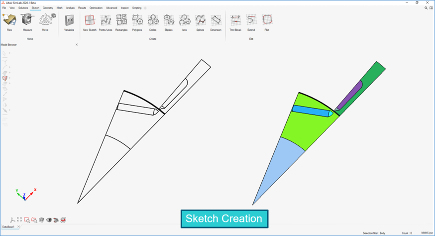
- The new ribbon” Sketch” is added. It contains the sketch tools to create 2D sketches with design variables.
- SimLab learning center (SLC) video – https://altair-2.wistia.com/medias/z9j7pedz1lFigure 2.
Geometry
- New Features
-
- Extract Facets from CAD
- Added a new tool to extract facets from CAD bodies.
- Enhancements
-
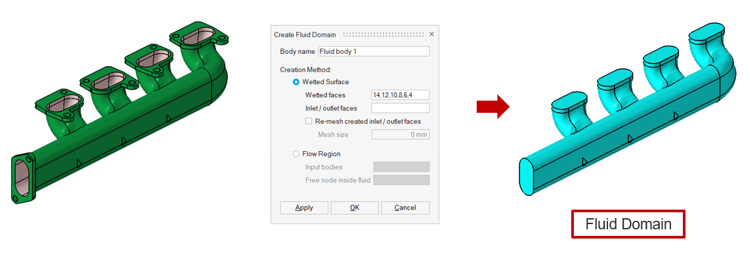
- Create Fluid Domain
-
- Support added to create Fluid Domain for CAD (Parasolid imported with “Save Geometry in Database”).
- Added an option to create a fluid domain by
selecting the body and the orphan node inside the
fluid region.Note: The fluid region should be enclosed without leaks.Figure 3.
- Fix Intersections
-
- Support added to show within body intersection for CAD bodies.
- Renamed the tool name “Modify Intersections” as “Fix Intersections”.
- Dialog design is improved.
- Boolean
-
- Support added to transfer below mesh control
automatically from CAD to the connected body.
- Body mesh control
- All face and edge-based mesh control (except symmetry, hardpoints and edge mesh control bias seeding)
- Support added to retain the face and edge groups
after creating the connected body.Note: Groups will be retained only if the Parasolid model imported with “Save geometry in database”.
- Support added to transfer below mesh control
automatically from CAD to the connected body.
- Merge Models
- Support added to merge Parasolid models imported with “Save Geometry in Database”.
- Merge Faces
- Added support to merge faces in Parasolid bodies imported using save geometry in the database.
- Parasolid Imprint
- Added support to imprint Parasolid bodies imported using save geometry in the database.
- Unmerge Body
-
- Supported to unmerge multiple bodies.
- Added the support to transfer Material and Property to the unmerged bodies.
- Added support to unmerge the connected CAD
body.Note: This feature is supported only for the Parasolid model imported with “Save geometry in database”.
- Edge Offset
-
- Enhanced the edge offset tool to improve mesh quality.
- Robustness in improved in edge offset tool.
- Select Connected Faces
-
- Enhanced the tool to select the connected faces from one or more given input elements/faces.
- Support added to select connected faces from the Parasolid model imported with “Save geometry in database” option.
- Join
-
- “Overlapping faces” option is made default in the join tool. Earlier, the user must turn on “Show overlapping faces option in Assembly | Connect | Join” toggle to enable this option in the join tool.
- This option will capture and join both uniform and arbitrary overlapping surfaces.
- Body and face input are supported for joining overlapping surfaces.
- Supported local remesh.
- Create Body from Faces
- “Duplicate and make non-shared faces” option supported for Parasolid bodies imported with “Save geometry in database”.
- Remove Holes
-
- Support added to remove holes from Parasolid bodies imported with “Save geometry in database” option.
- Redesigned the remove hole dialog. Now, holes will
be removed from both CAD (Parasolid) and mesh
bodies.Note: “Parasolid: Features” tool is removed.
- Break Faces
- Break faces tool is supported for Quad elements.
- Simplify
-
- In case of a single body as input, the input body name is retained for the simplified body.
- Undo supported.
- Added an option to create the simplified
CAD(Parasolid) body.Note: If the input is a Parasolid body imported with ‘Save geometry in database’ option enabled, the simplified CAD body will be created in the input model itself. Otherwise, it will be created in a new Parasolid model.
- Resolved Issues
-
- Split Face
- The existing LBCs/mesh control/groups are not retained after the split face. This is fixed.
- Simplify
-
- Fixed the issues in updating the axis orientation and cylinder attributes for simplified cylinder bodies.
- Fixed the issue in aligning the simplified box bodies with respect to the input body.
Mesh
- New Features
-
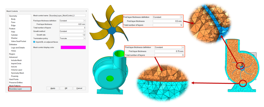
- Mesh Controls
- Added boundary layer mesh control to define various boundary
layer parameters for different domains.Figure 4.
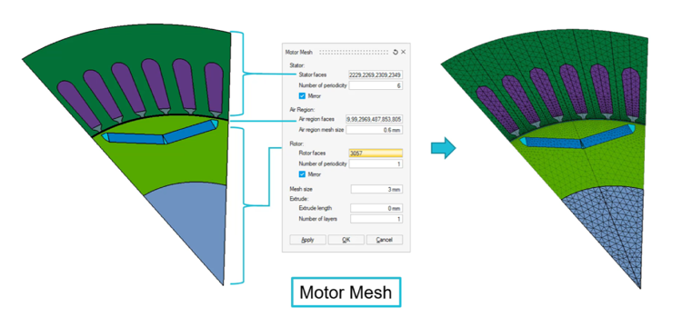
- Motor Mesh
- Added a tool to create symmetry mesh for motor cross
sections.Figure 5.
- Hex Local Re-Mesh
- Added a tool to support re-meshing on a hex meshed body.
- 2.5D Hex Mesh
- Added a new tool to generate Hex and Wedge mesh for 2.5D Bodies.
- Pipe Mesh
- Added a new tool to Hex mesh the various cross-sectional pipes bodies with reference cross-sectional mesh.
- Cartesian Hex Mesh
-
- Added a new tool to create Hex Mesh to capture the geometry approximately.
- Supported the below Mesh Types.
- Isometric Mesh – Mesh size will be the same in all direction.
- Anisotropic Mesh – Different mesh size can be defined for each direction.
- Enhancements
-
- Mesh Controls
-
- Cylinder mesh control: Option added to specify “element size” for the circumference of the cylinder.
- Preserve Entities: Support added to preserve nodes while performing Quad mesh.
- Surface Mesh
-
- Turning off the “Create mesh in new model” option
from advanced options, will create the mesh bodies
to one model and it is now enhanced to keep one mesh
for each cad.
- If the cad body meshed again and again, the previous mesh body will be replaced with a new mesh body.
- Added an option to “Allow quad mesh transition” which allows the mesh transition during Quad mesh.
- Turning off the “Create mesh in new model” option
from advanced options, will create the mesh bodies
to one model and it is now enhanced to keep one mesh
for each cad.
- Local Re-Mesh
- Added an option to “Allow quad mesh transition” which allows the mesh transition during Quad mesh.
- Wrapper Mesh
-
- Redesigned the user interface of the dialog.
- Added new options
- Region excluding solid mesh in Internal (Cavity)
- External and Internal cavity
- Improved the performance and robustness of the tool.
- Change Layers
-
- Added support for hex mesh bodies containing wedge elements along the bounding edges.
- Added support to give disconnected element edges/edges as input for change layers.
- Initial Mesh
-
- Added a toggle to enable faster meshing for Parasolid bodies.
- Removed “Auto Assembly” option.
- Mid Mesh
- Supported quad mesh transition option.
- Edges
- Supported value remembrance for Free Edge and Non-Manifold toggles.
- Quality Check & Quality Check (New)
- Improvements done to compute the quality for visible bodies. Visible bodies should be from the same model.
- Quality Check (New)
-
- Updated the conditions to maintain consistency with the old quality check.
- Support added to modify the limit value in the dialog.
- Equivalence Nodes
-
- Support added to display the equivalenced nodes regardless of node count.
- Earlier, only 10,000 equivalenced nodes could be displayed.
- Tet Mesh
-
- Renamed “Volume Mesh” to “Tet Mesh”.
- Turning off the “Create mesh in new model” option
from advance, will create the mesh bodies to one
model and it is now enhanced to keep one mesh for
each cad.
- If the cad body meshed again and again, the previous mesh body will be replaced with a new mesh body.
- Removed Wedge6 and Hex8 options. These options are moved to the ‘2.5D Hex Mesh’ tool.
- Enhanced the “Assembly” option to retain the merged bodies during Tet mesh. Earlier, merged bodies will be unmerged during Tet mesh.
- Enhanced the “Mesh as single body” option to retain the merged disconnected bodies during Tet mesh. Earlier, merged disconnected bodies will be unmerged during Tet mesh.
- Turning off the “Create mesh in new model” will
create the mesh bodies to one model and it is now
enhanced to keep one mesh for each cad.
- If the cad body meshed, again and again, the previous mesh body will be replaced with a new mesh body.
- “Fill hollow space in solids when volume meshing” option is removed from preferences dialog and added this option under Tet mesh dialog under advanced options.
- Also, renamed “Fill hollow space in solids when volume meshing” to “Fill cavity inside volume".
- Hex Mesh
-
- Hex Mesh related tools are grouped and placed under this ribbon.
- Enhanced PCB mesh tool to generate Mesh for PCB’s having sharp corners in it.
- Auto Extrude
- Added an option “Allow quad mesh transition” to allow the mesh transition.
- Mid Mesh
- Added an option “Allow quad mesh transition” to allow the mesh transition.
- 2.5D Hex Mesh
-
- Added an option to “Allow quad mesh transition’ to allow the mesh transition.
- Mesh robustness is improved.
- Identify Bodies to Hex Mesh
-
- Improved the robustness of 2.5D and PCB multiple body identification.
- Enhanced the tool to identify the cyclic symmetric bodies using the “Axis symmetric” option.
- Auto Hex Mesh
-
- Added support to mesh the PCB multiple bodies automatically.
- Enhanced the tool to have uniform mesh on concentric circles for 2.5D bodies.
- Enhanced the tool to capture geometry properly for 2.5D bodies.
- Support added to hex mesh the uniform sweep bodies.
- Added an option “Allow quad mesh transition” to allow the mesh transition.
- Mesh flow improved on cylindrical faces to improve the quality.
- Mesh robustness is improved.
- Support added to mesh Identical bodies as instances when "Find identical bodies and mesh as instances" toggle is enabled in File > Preferences > Mesh.
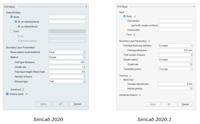
- CFD Mesh
-
- Added support to retain the input merged bodies after boundary layer creation. Earlier, it will be unmerged.
- Double precision meshing is enabled by default for CFD meshing.
- Enhanced the UI to reduce the manual effort for
users to give inputs.Figure 6.
 Body option
- Can mesh multiple connected fluids and solid bodies in one click.
- The input requirement is to have bodies that do not have any free edges and element intersections.
Face option- This option takes faces as the input. Users can select all the faces of the bodies to mesh.
- Faces from sheet Bodies can mesh.
- If faces from multiple volumes, then the user needs to create nodes inside target fluid volumes for Mesher to identify and generate BL inside them. The remaining volumes will be Tet meshed assuming they are solid volumes.
- The total number of bodies may reduce as it will create closed volume mesh bodies.
- In both meshing options (Body & Face), User need to select only faces that does not require a BL (Example: inlet faces, outlet faces, shared faces between fluid bodies). All the remaining faces in selected fluid bodies will get a boundary layer.
- BL First Layer Height can be defined in 2 ways:
- Constant: This takes a constant value and this value is applied for the entire model.
- Fraction of Surface Mesh Size: The first layer height for each element equals the average element size multiplied by the given factor. This option is useful when the mesh size of 2D elements varies significantly and constant first layer height is not needed. A smooth BL to tetra mesh transition for all elements can be achieved by using this option.
- Three different Growth methods are available:
- Constant: This will determine boundary layer growth based on a constant ratio such as growth rate.
- Variable: This provides constant growth for the first few layers from the wall and after that, the growth rate will increase based on a multiplication factor until the maximum growth rate is achieved.
- Match Outer Layer: This provides a constant growth rate for the first few layers from the wall and the growth rate of remaining layers will be adjusted such that the final BL size matches with the core volume mesh size. This method helps to obtain a smoother transition from the boundary layer mesh to volume mesh.
- BGA
- Support added to create BGA using CAD/FEM (Sphere body) as
input.Note: Input sphere bodies should have the same radius with sphere attributes.
- Voxel Mesh
-
- Support added to auto-update the mesh size value once the input body is selected.
- Performance is improved.
- Resolved Issues
-
- Mesh Controls
-
- IsoLine Mesh Control
- Due to the incorrect CAD attributes on isoline mesh control assigned faces, surface mesh failed. This is fixed.
- Isoline mesh control assigned faces got affected due to the maximum element size in surface mesh. This is fixed.
- Hard Points Mesh Control
- Hard points will not be considered even if the tolerance value is increased. This is fixed.
- Fixed the bad mesh output when hard points are applied.
- IsoLine Mesh Control
- Re-Mesh
- During CAD local re-mesh, orphan nodes are created. This is fixed.
- Grid Mesh
- The mid nodes present in the adjacent faces were linearized. This is fixed.
- Tet Mesh
- Volume mesh affects the shared face mesh if there exists a “Volume layer” mesh control. This is fixed.
- CFD Mesh
- Resolved the volume mesh failure of BL mesh input when using the “Mesh as single body” option.
Solution
- New Features
-
- Application > Electronics Thermal Management
- Added support to setup Electronic Thermal Management solution using ElectroFlo Solver.
- Enhancements
-
- Moved the Solutions ribbon to the front of all the ribbons and default ribbon in SimLab.
- Supported creating Fatigue and Optimization solution from
solution ribbon.Note: These solutions can be created only when the database contains at least one Optistruct solution.
- Mesh Convergence is moved from right click in Parameter browser
to Solution ribbon.
- Added option to ignore regions where we do not want mesh refinement.
- Plot option to show responses against each iteration.
Figure 7.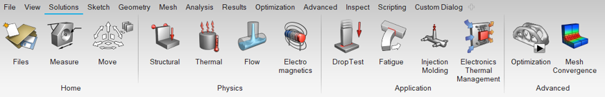
Analysis
- Enhancements
-
- Pressure
- Separated the amplitude table from the distributed pressure table list and added a new option to link the amplitude table.
- Initial Condition
- Removed marker display for all initial conditions, it helps to visualize the model clearly.
- Bearing Pressure
- Support added to define Force components in the Bearing pressure load using the local coordinate system.
- Mapping
-
- Mapping of heat source load data from the Feko is supported.
- Supported mapping of initial conditions - Velocity, pressure, species proportion coefficient from nFX to AcuSolve Solution.
- Option added to specify the unit system of the input data. This helps to map and visualize the output in user desired unit system.
- Replace Bodies
-
- Bodies can be replaced in Solutions.
- Loads and boundary conditions applied on the current body, will be listed from the current solution only.
- Once loads and boundary conditions are transferred successfully from current to new body, the current body will be removed, and the new body will be added to the current solution.
- Resolved Issues
-
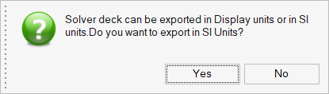
- Export and Solve
- During export, the solver deck can be exported in SI unit
irrespective of the displayed unit to maintain consistency
in results. Question will be posted during export, whether
to export in displayed unit or SI unit.Figure 8.
- Material
- The Hyperelastic material table relation for the Volumetric Stress table is changed to Closure Vs Pressure.
Solver Interface
- OptiStruct
-
- Solution > Physics > Structural
- Added support to create Tie contacts automatically while creating Linear or Normal mode solutions.
- OptiStruct Solution > Loadcase > Right Click > Enable / Disable entities
-
- Support added to include or exclude MPC to load cases.
- Support added to include Contacts for Nonlinear load cases. Also, the contact parameters can be specified with respect to each load case.
- OptiStruct Solution > Results > Update
-
- Support added to view the Solver log file while solving.
- Added support to export a log file
(<SolverFileName>_Name_ID_Information.csv)
automatically while solving or exporting the solver
deck. This log file has below details about the
solution setup.
- Name of Loads or Boundary Condition, corresponding card name and its IDs
- Loadcase name and its loads and boundary conditions
- OptiStruct Solution > Right Click > Compute Fatigue Life
- Added support to compute fatigue life for Non-Linear static solutions.
- Analysis > Loads and Constraints > Loads > Hydrostatic Pressure
- Added a new tool to define and export hydrostatic pressure.
- Analysis > Property > Material
-
- Added support to define the Engineering Stress vs
Stretch Ratio table for OptiStruct Hyperelastic
material test data.Note: If Engineering Stress vs Engineering Strain table is defined for OptiStruct solution, while exporting the solver input file, it will convert the Engineering Strain values to Stretch Ratio based on the below relation:
Stretch Ratio = 1 + Engineering Strain
- Added support to define, import and export of Orthotropic material using Engineering constants (MAT9OR).
- Added support to define, import and export of Temperature dependent Orthotropic material using Engineering constants (MATT9OR).
- Added support to define the Engineering Stress vs
Stretch Ratio table for OptiStruct Hyperelastic
material test data.
- AcuSolve
-
- Immiscible Multiphase Solution
-
- Support added to define the Multiphase (levelset) to handle two different immiscible fluids.
- Multiphase material can be defined for segregating two immiscible fluids.
- Initial condition can be used to define a region for one immiscible fluid .
- Added support to define incoming fluid and backflow incoming fluid for inlet and outlet.
- Disperse Multiphase Solution
-
- Support added to define Disperse Multiphase solution to handle different disperse phases with a carrier fluid.
- Maximum 5 disperse phases can be added along with carrier fluid.
- Initial volume fraction for carrier fluid and disperse phases can be defined in Initial condition.
- Inlet and Outlet backflow volume fraction can be defined for carrier fluid and disperse phases.
- Humid Air Modelling
-
- Support added to define Humid Air modelling. Humidity will be listed only when heat transfer is enabled.
- Humid Air material will be created automatically once the solution is defined with Multiphase humidity.
- Initial humidity and humidity film thickness can be defined in initial condition.
- Inlet humidity boundary conditions can also be
defined.Note: Humidity film thickness option will enable for transient flow type only.
- AcuSolve - nFX Coupling
-
- Supported model setup for nFX – AcuSolve simulation.
- Added support to map the nFX point cloud data as AcuSolve initial conditions.
- Solution > Physics > Flow
- Support added to define Gravitational Acceleration.
- Analysis > Boundary Conditions > Radiation > External Radiation
- Added support to create external radiation surface boundary condition.
- Analysis > Boundary Conditions > Radiation > Solar Radiation
- Added support to apply the Solar Radiation Surface boundary condition on Thin Solid.
- Analysis > Boundary Conditions > Domain > Porosity
- Added separate dialog for Porosity. This helps the user to define permeability based on local Cartesian or cylindrical or spherical coordinates.
- Analysis > Boundary Conditions
- Markers are supported for the following boundary
conditions:
- Body force
- Periodic
- Heat source
- Solar radiation surface
- Contact resistance
- Thin solid
- Analysis > Material
- Support added to define Orthotropic cylindrical conductivity.
- AcuSolve Solutions > Right click > Format and Spawn Options
-
- Added an option “Auto Wall” to export wall boundary condition with default parameters. This wall boundary condition will be assigned to the faces which contain no boundary conditions.
- Added support to define Pressure Reference Node to export zero pressure nodal boundary condition in absence of inlet and outlet for fluid volume.
- AcuSolve Solution > Results > Update
- Support added to view the Solver log file while solving.
- Render mode > Color > CFD
- Added support to displays the color for the entities of
Boundary Conditions instead of showing markers. Below
boundary conditions are support with colors.
- Flow
- Radiation
- Thin Solid
- Mesh Displacement
- Radioss
-
- Radioss Solution > Results > Update
-
- Support added to solve Radioss solutions in the background without freezing SimLab while solving.
- Added support to view the Solver log file while solving.
- Radioss Solution > Right Click > Export Specification File
- Added support to export the Radioss solution setup as a template.
- Radioss Solution > Right Click > Result Request
-
- Added support to request result in H3D format.
- Below nodal output requests are supported:
- Time Step
- Internal forces
- Contact pressure
- Mass variation
- Below element output requests are supported:
- Von mises stress
- Pressure
- Density
- Below Time History requests are supported:
- Node
- SHEL
- SH3N
- BRIC
- Radioss Solution > Right Click > Solution Parameter
-
- Time step control option is support for TET4 elements.
- Added an option to stop computation when element quality reaches negative volume.
- Added an option to stop computation when energy error ratio criteria, total mass ratio criteria or nodal mass ratio criteria are achieved.
- Option added to control parallel arithmetic.
- Analysis > Loads and Constraints > Coordinate
- Supported added to export Local coordinate system /SKEW.
- Analysis > Loads and Constraints > Force
- Support added to export force load /CLOAD.
- Analysis > Loads and Constraints > Constraints > Enforced
- Added support to export and import of rotational enforced constraints.
- Analysis > Property > Material
- Support added to define below material:
- /MAT/LAW62
- /MAT/LAW70
- /MAT/LAW69
- /MAT/PLAS_ZERIL
- Flux
-
- Transient Magnetic Solution
-
- Support added to define transient magnetic solution specifically for Electric motor applications.
- The solution is controlled by time or angle.
- Analysis > Transient Magnetics Loads > Circuits
-
- Circuit templates are added to define the circuit definitions.
- Three Phase - without squirrel cage and with squirrel cage circuits are added.
- Flux Solution > Results > Update
- Support added for background solve and viewing the Solver log file while solving.
- Molding
-
- Molding Solution > Hot Runner Systems
- In this release hot runner systems are supported. This includes creating hot runner assemblies and tools for specifying controllers to open/close the valves and heater settings to control the temperature in the hot runners.
- Molding Solution > Analysis > Valve Controller
- A new boundary condition, “Valve Controller” is added to specify valve settings. This is used to specify the valve initial state and the controls to open/close the valve during the filling stage. Valve settings for packing and cooling stages are written based on default settings.
- Molding Solution > Analysis > Heater Controls
- A new boundary condition, “Hot Runner Heater” is added to specify heater control on the hot runner surfaces. This is used to specify the mechanism used to control the heater.
- Molding Solution > Format and Spawn Options
-
- Export options for packing stop criteria are reorganized to correctly specify the conditions.
- Added support to input the number of processors used by the solver.
- Export options now support units.
- Molding Solution > Materials
-
- More than thirty materials supplied by M-BASE for generic polymers are included in this release.
- Polymer materials now support a new temperature dependence named “Normalized WLF Model” for Carreau-Yasuda viscosity models.
- Molding Solution > Results > Update
-
- The solving method of the Molding solution is modified and made consistent with other solvers.
- Support added to view the Solver log file while solving.
- ElectoFLo
-
- UI > Face Right Click
-
- Added a new option “Create mesh planes” to maintain planar faces while generating Cartesian Hex Mesh.
- Mesh plane creation is supported only for the planar faces aligned to the global axis.
- View > Output Window
- Support added to print the fine mesh element count in the output window while exporting or solving ElectroFlo solutions.
- ElectroFlo Solution > Right Click > Solution Parameters
-
- Added mesh parameters.
- Maximum First Layer Height - Minimum element edge size
- Maximum mesh size - maximum element edge size
- Grade Factor - Growth rate for attaining maximum mesh size from maximum first layer height
- Aspect Ratio - Each element aspect ratio should not be more than the specified aspect ratio
- Fine Mesh - To create a fine mesh.
- Coarse Mesh - To create a coarse mesh.
- Added solver parameters.
- Added mesh parameters.
- ElectroFlo Solution > Results > Update
-
- Background solve is supported.
- Support added to view the Solver log file while solving.
- Analysis > Boundary Conditions
- Markers are supported for below boundary conditions:
- Voltage
- Current
- Radiation
- Render mode > Color > CFD
- Added support to displays the color for the entities of
Boundary Conditions instead of showing markers. Below
boundary conditions are support with colors:
- Temperature
- Flux
- Convection
- Radiation
- Voltage
- Current
- Results GUI > Results Panel
- Supported to display the ElectroFlo elemental results in weighted averaging method.
- Abaqus
-
- Solution > Physics > Structural
- Added support to create Tie contacts automatically while creating Linear or Normal mode solutions.
- Abaqus Solution > Results > Update
- Support added to view the Solver log file from solved solution.
- Analysis > Loads and Constraints > Contact
- Added support to define Circumferential surface smoothing parameters and Contact Initialization parameters for General Contact.
- Analysis > Property > Material
-
- Supported export and import of Hyper-Elastic material definitions.
- Supported Mooney-Rivlin, Ogden and Arruda-Boyce models in Hyper-Elastic Material.
- Added support to define the Engineering Stress vs
Engineering Strain table for Abaqus Hyperelastic
material test data.Note: If Engineering Stress vs Stretch table is defined for Abaqus solution while exporting the solver input file, it will convert the Stretch Ratio values to Engineering Strain based on the below relation:
Engineering Strain = Stretch Ratio – 1
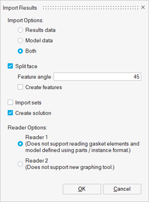
- File > Import > Results > Abaqus
- Added support to import Abaqus results file (.odb) with
either new results reader (Reader 1) or old results reader
(Reader 2).Figure 9.
- LsDyna
-
- Analysis > Tools > Sets
- Support added to import and export of following sets in
LsDyna solver:
- Node
- Shell Element
- Solid Element Face
- Solid Element
- Permas
- Removed import and export support for BIF and BIFO formats.
Optimization
- Enhancements
-
- Design Space
- Support added to define Overhanging design space constraint for topology optimization.
- Response
- Support added to define PSD and RMS response, to perform random response optimization.
Results
- New Features
-
- Iso Surface
- Support added to display iso surface results.
- Animation Toolbar
- Supported “Modal animation mode” for H3d results.
- Enhancements
-
- Results Panel
- Support added to define Variation (%) for Results Averaging method from the Results panel
- XY Plot
- Support added to retain user plot attributes like Title, X-axis, Y-axis, and Graph settings.
- Resolved Issues
-
- Results Panel
- The results panel is missing while capturing the image using File > Camera. This is fixed.
- Deformed View
- Fit view was not working properly for deformed results. This is fixed.
- Results legend bar
- Contours are not updated if the value is edited in the legend bar. This is fixed.
- Animation toolbar
- After solving OptiStruct solution, the results deformation was incorrect. This is fixed.
Advanced
Bolt Modeling
- Resolved Issues
-
- Bolt Head / Thread
- Performance improved in selecting the input edges for bolt head and thread creation.
Testing
- New Features
-
- Compare files
-
- Added a new tool to compare files.
- Text: To compare text files, solver input file, etc.
- Gda: To compare the mesh properties between
output and reference “.gda” file present in the
system.
- The topology option will compare the regular topology details like face, edge., with the additional choice of mesh orientation, node position and solid nodes.
- Node count option will only compare the surface and solid node count based on user specified “Allowed difference in the count”.
- Regression Test
-
- Added new tool to run regression test using scripts (Python, Jscript, XML & SLS).
- This regression test will be run in batch mode. User can continue to work on current SimLab session while execution.
- By default, basic regression scripts will be displayed in the dialog. Before shipping the delivery to customer, we can run the basic regression script and confirm the stability.
- Also, user-defined script location can be pointed and execute the scripts.
Figure 10.
Weld
- New Features
-
- Create Plug
- Added a new tool to create plug weld.
- Create Weld Bead
- Solid Weld Bead Option page is moved as separate dialog as Create Solid Weld Bead and hex and Tet section images shown accordingly.
- Enhancements
-
- Connect weld to body
- Added an option to create Heat Affected Zone (HAZ) as a separate body, which can be used for post-processing.
UI Customization
- Enhancements
-
- Dialog Designer
-
- Redesigned the UI.
- Layout option is added to group the options.
- Unit support is added.
- Added option to assign icons to the custom dialog.
- All the customized dialog will be listed under ‘Custom Dialog’ ribbon.
Figure 11.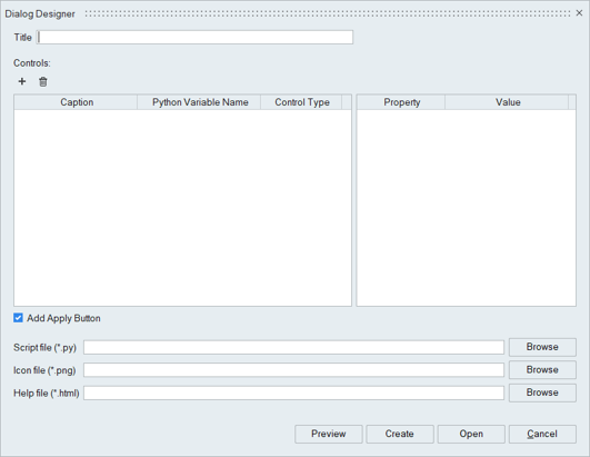
nanoFluidX Application
- Enhancements
-
- SimLabExternalSolverInterface license feature is no longer required to access nFX profile.
- Help links updated to nanoFluidX 2020 online help.
- Time history tables are supported for Domain (Body Force), Inlet Regions, Outlet Regions, Impose Regions.
- Every menu now includes an “Advanced Options” text box to allow manual input of parameters which are written directly into the .cfg.
- Mass flow planes are no longer supported, and the corresponding material and tools have been removed.
- Resolved Issues
-
- Domain
-
- Domain | Body force had incorrect default value when units were active.
- BC Type = Open is no longer supported and has been removed.
- Inlet Regions
-
- Inlet Phase is written incorrectly when no particles are present.
- Inlet Region object can’t be moved when section cut is active.
- Motions
- Motion centre exported incorrectly when Units were active.
- Probes
- Solid Probe move with command was not exported properly.
- One Click SPH Creation
- nFX particle generation failed on certain hardware/OS combinations.
- Remove Duplicate Particles
- Fixed the performance issue.
- Render Mode > Color > Material
- Point body is not displayed with the material or Property color. This issue is fixed.
- Solution Settings
-
- RM_freq_rho_reinit was always exported as zero.
- Transport Velocity will now always be deactivated when Interaction Scheme is set to Riemann.
Scripting
- New Features
-
- Result Simulations
- Added a utility function “getResultSimulations” to get all the list of Simulations in a load case.
- Activate Results
- Added a utility function “activateResults” to activate the result using load case name, simulation name, component and subcomponent Name.
- Update Contour for Bodies
- Added a utility function “updateContourforBodies” to get minimum, maximum results value and update contour for selected bodies.
- Update Legend Settings
- Added a utility function “updateLegendSettings” to update the results legend using the number of segments, the format of result number, the precision of result number, user defined interval values and its color of each segment.
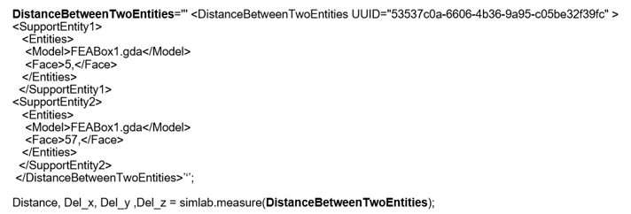
- Measure Distance
- Added support to calculate the distance between entities
using the below python utility.Figure 12.
- Get Next Node ID
- Added a utility function “getNextNodeID” to get the next available node ID to be created for the given model.
- Cutting Plane Views
- Enhanced “simlab.enablecuttingPlane” utility to enable the cutting plane views.
- Capture plot image – Results > Distortion > Bore
- Added a utility function “simlab.capturePlotImage” to save the Bore Distortion graph plots as images in a specified location.
- Clear Selection
- Added Utility function “deselect” to deselect Geometry / FEM / Group entities in UI.
- Parameters
- Added generic utility “getParameter” to get the values of SimLab and Sketch parameters.
- Enhancements
-
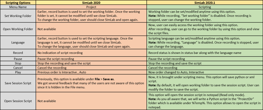
- Scripting Menu
- “Project” menu is renamed as “Scripting” and design is
improved.Figure 13.
- Auto Play
- Script execution log file is enhanced to have the script name in it. It used to be “ProjectLogFole.txt” before, now it will be “<script_name>_LogFile.txt”.
- Interactive Play
- While execution the XML scripts in interactive mode, Units system will be displayed inside the interactive dialog, in which the script was recorded.
- Delete Mesh Control
- Supported to delete all mesh controls while executing the script that has empty value for the tag “<Name value=>” in delete mesh control process.
- Capture Image
-
- Added support to capture coordinate and legend as a separate image.
- Also, the model can be captured in an image, with or without results panel and legend.
- After recording the capture image function, the user should manually edit the script to perform the above option.