Element Orientation
You can select an orientation vector and apply it to all newly created elements.
-
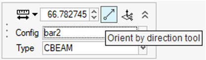
From the microdialog, select either the default
orientation or select a vector tool to define the orientation.
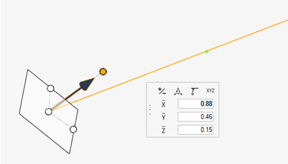
Figure 1.
-
Use the Vector tool to define orientation vector. The default is to global
Z.
Figure 2.