Create 2D Surface Mesh
Use the General 2D Mesh: Create tool to create a surface mesh and remesh elements.
A surface mesh or "shell mesh" represents model parts that are relatively two-dimensional, such as sheet metal or a hollow plastic cowl or case. Surface meshes are placed on the outer faces of solid objects, and are used as a baseline mapping point when creating more complex 3D meshes (the quality of a 3D mesh largely depends on the quality of the 2D mesh from which it is generated).
General 2D Mesh should be the default surface mesh tool selected. To view a drop-down menu of available surface mesh methods, click the arrow on the right side of the tool.
-
From the Mesh ribbon, click the General 2D Mesh tool.
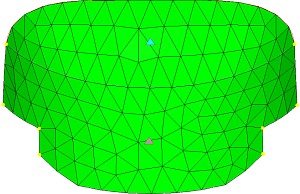
Figure 1.
 By default, the Create should be selected from the secondary ribbon.
 - Optional:
On the guide bar, click
 to define surface mesh options.
General 2D Mesh: Create Tool
An overview of the General 2D MeshInteractive: Create tool.
Use the General 2D Mesh: Create tool to create a surface mesh and remesh elements.
- Access
- Go to .
Options
- Element size
- Set the average element size.
- Mesh type
- Select the algorithm to use for generating the mesh.
-
Select the type of element to use during mesh creation.
- Mixed
- Uses quads primarily, but inserts trias when making density transitions,
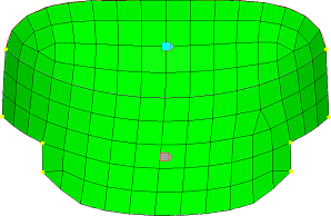
resulting in improved mesh quality.Figure 3. Example: Mixed Elements
- Quads
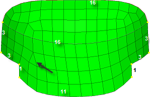
- Attempts to use quads only, however, at least one tria element must be
created if the sum of the element densities around the perimeter of the
face or surface is odd.Figure 4. Example: Quad Elements. The sum of element densities on the perimeter of the lower surface is odd, resulting in a tria.
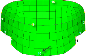
- Adjusting the element densities while meshing interactively can usually
eliminate all tria elements.Figure 5. Example: Quad Elements. Adjusting the bottom edge density from 11 to 10 makes the sum even and generates all-quads.
- Quads only
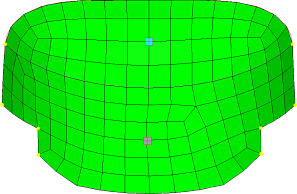
- Uses a subdividing routine that tends to generate more orthogonal quad elements.
- Tria elements may still be introduced depending on the density
settings.Figure 6. Example: Quad Elements Only
- Tria
- Uses all trias to mesh.Figure 7. Example: Tria Elements
- Advanced
- Choose any of the other types individually for mapped elements (elements on surfaces that can be mapped to simple geometric shapes) and free elements (those that cannot easily map to simple shapes).
- Element type
- Specifies the type of elements used to create the mesh.
- Edit criteria
- Edit the criteria file via the Criteria Editor
- Element order
- Specify whether or not to create mid-edge nodes.
- Active mesh mode
- Select the meshing mode, with interactive allowing access to the mesh editing tools.
- Curvature based refinement
- Option to turn on mesh refinement based on geometric curvature.
- Method
- Select the adaptive meshing method.
- Minimum size factor
- The minimum element size, as a factor of the average element size. Value must be less than or equal to 1.
- Span angle
- Maximum deviation factor
- The maximum allowable deviation between an element edge and a geometry edge, as a factor of the average element size.
- Feature angle (adaptive mesh)
- The maximum allowable break angle between adjacent elements.
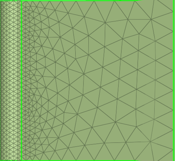
- Growth rate
- The factor to control the rate of transition in case of element size
change.Figure 8.
- Minimum edge density
- Enable a minimum number of elements along an edge.
- Minimum density
- Set the minimum number of elements created along an edge.
- Apply if edge length <
- Apply a minimum edge density when edge lengths are less than the specified value.
- Link opposite edges method
- Select the method for linking mesh settings on opposite edges of rectangular surfaces.
- Features detection
- If Connected, feature edges will be auto-detected by specifying the connected feature detection algorithm (as in the Features panel), 1D elements which are part of 2D mesh edges, and existing FE edges with nodes already associated with surface edges.
- Feature angle
- Define a maximum angle across which elements can be maintained.
- Vertex angle
- Define the angle used for breaking feature-edges into simpler segments. This is the feature angle for common edge smoothing.
- Aspect ratio <
- The maximum aspect ratio to allow when linking edges.
- Orthogonal alignment
- Generates a more orthogonal quad-dominant mesh
- Minimum size variation
- Enforce a global mesh element size with minimal min/max element size variations.
- Size variation
- Keep elements roughly the same size.
- Skewness
- Prevent the mesh from producing highly-skewed elements.
- Smooth across common edges with
- Allow node smoothing to move nodes across adjacent surface edges whose feature angle is less than the value specified.
- Feature angle (advanced)
- The feature angle for common edge smoothing.