Contact Interfaces
What is the meaning of: WARNING ID 94 and WARNING ID 477
WARNING ID :           94
** WARNING IN INTERFACE GAP
DESCRIPTION :
   -- INTERFACE ID : x
   -- INTERFACE TITLE : xxx
   INPUT GAPmin xxx > (MINIMUM MASTER ELEMENT EDGE LENGTH) / 2
   FOR SELF CONTACT, ARTIFICIAL STIFFENING CAN OCCUR IF AN ELEMENT IS COMPRESSED
   TO PREVENT THIS WARNING, DEFINE GAPmin < xxx
  POSSIBLE IMPACT NUMBER:        xxx  (<=           2 *NSN)
- Minimum master element edge length
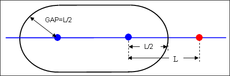
Figure 1.
Therefore, it is recommended to define .
If , a self-contact will be detected which generates contact forces from the beginning of the computation. Such a situation can be accepted if it is local enough, but not if it is a frequent situation over the self-impacting interface. It is possible to find the source of this message by using a pre-processor and selecting the elements through size criteria.
WARNING ID :          477
** WARNING IN INTERFACE GAP
DESCRIPTION :
   -- INTERFACE ID : x
   -- INTERFACE TITLE : xxx
   MAXIMUM VARIABLE GAP xxx > (MINIMUM MASTER ELEMENT EDGE LENGTH)/2
   FOR SELF CONTACTS WHERE THE VARIABLE GAP IS LARGE AND THE ELEMENT EDGE LENGTH IS SMALL
   ARTIFICIAL STIFFENING CAN OCCUR DURING ELEMENT COMPRESSION
SOLUTION :
TO PREVENT THIS ISSUE, USE Igap=3 TO AUTOMATICALLY REDUCE THE GAP BASED ON ELEMENT SIZE
  POSSIBLE IMPACT NUMBER:        xxx  (<=           1 *NSN)
This warning message is like the constant contact gap warning except in this case the maximum variable gap for the entire contact is used in the check, . This warning isn’t as precise because it is very possible that the maximum variable contact Gap is in a different location then the minimum element length and therefore no problem exists in the model.
- Length of the smaller edge of element connected to the master
- Length of the smaller edge of element connected to the slave node
- Percentage of mesh size, default=0.4.
and the warning message will no longer be output.
What is the meaning of "Infinite domain detected"?
This message can be written by Radioss Engine.
Such an error message may appear during sorting of contact interfaces when the distance between some nodes of the model becomes infinite.
One has to look at the model behavior to understand why some node coordinates are infinite. One common explanation is "flying" nodes after failure of elements belonging to interface surfaces. In this case using Idel =2 in contact interfaces should fix this problem.
What does the parameter Bumult in the input cards for an interface correspond to?
Detecting the slave nodes and master segments which are in contact, a spatial sort is necessary. Even if using high performance sort algorithms, a full sort at each cycle would not be a fast enough solution. So during sorting, impacts within some security distance up to the gap are retained.
The frequency of interface sorting, that is to say the security distance up to the GAP for storing the candidates to the impact, relies on the parameter Bumult.
It is recommended not to change its value (which is by default 0.20), since it has been determined in order to optimize the performances, based upon our experience.
What is the meaning of WARNING ID: 460, in the output file (Runname_0000.out)?
WARNING ID: 460
** WARNING IN SIZE OF INFLUENCE ZONE
INFLUENCE ZONE IS TOO BIG COMPARED TO ELEMENT SIZE,
MULTIMP SHOULD BE GREATER THAN 12 FOR INTERFACE 1,
OR THE VALUE OF THE GAP SHOULD BE DECREASED (SEE RECOMMENDED GAP)
POSSIBLE IMPACT NUMBER: 0 (< = 1 * NSN)
For each interface, Radioss Starter estimates the necessary memory size in case all slave nodes would impact the master surface at the same time. This memory size would be more important if the GAP is big, with respect to the master elements size, since an impacting node would impact a larger number of master elements at the same time.
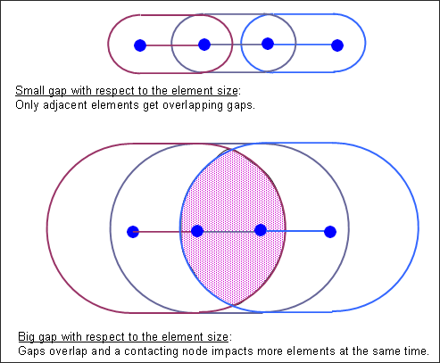
Figure 2.
When the interface TYPE2 is used to tie slave nodes (from tetra elements) to a surface (from tetra elements). Depending on which Spotflag used, why is the rigid body motion transmitted and not transmitted?
The situation is quite usual. The problem is that we tie slave nodes of tetra elements to segments on the tetra elements.
With Spotflag=0, you do not have balanced moments, therefore, the more distance between slave and master the worse (the higher) will be the unbalanced forces. Here the distance is app 15% of element size. A smaller distance will improve the situation. A larger distance will make it worse (general for solids and shells).
For the shell on the master side, the situation is better because the shell nodes have rotational DOF. The tetra nodes have no rotational DOF (they are infinitely stiff against rotation) and give too much resistance in the cases where the shell nodes would just rotate.
For Spotflag=1, you transfer the forces from the slave to the master nodes so that the force balance is assured and the level is not so high.
So, when using interface TYPE2 contact, if under-integrated solid elements connected through TYPE2 contact with Spotflag=0. This should be avoided.