/SPRING
Block Format Keyword Describes the spring elements. It used for modeling connection. The spring properties are apply on the local spring coordinate system.
Format
| (1) | (2) | (3) | (4) | (5) | (6) | (7) | (8) | (9) | (10) |
|---|---|---|---|---|---|---|---|---|---|
| /SPRING/part_ID | |||||||||
| sprg_ID | node_ID1 | node_ID2 | node_ID3 | node_ID4 | node_ID5 | node_ID6 | |||
Definitions
| Field | Contents | SI Unit Example |
|---|---|---|
| part_ID | Part identifier of the
block (Integer, maximum 10 digits) |
|
| sprg_ID | Element
identifier (Integer) |
|
| node_ID1 | Node identifier 1 for
spring (Integer) |
|
| node_ID2 | Node identifier 2 for
spring (Integer) |
|
| node_ID3 | Node
identifier 3
(Integer) |
|
| node_ID4 | Node
identifier 4
(Integer) |
|
| node_ID5 | Node
identifier 5
(Integer) |
|
| node_ID6 | Node
identifier 6
(Integer) |
Comments
- The identifier must be unique in each element family, but it is advised for each element type to have a unique element identifier in the global model.
- More than one spring block can be used to define a part.
- Any number of springs can be defined in one block.
- Spring elements with /PROP/TYPE8 (SPR_GENE) may have a length equal to 0.
- Spring elements with /PROP/TYPE12 (SPR_PUL) and /PROP/TYPE13 (SPR_BEAM) should have a non-zero length.
- Spring element is defined with two
nodes: node_ID1 and node_ID2.The plane XY is defined with the three nodes (node_ID1, node_ID2, and node_ID3); the third node, node_ID3 defines the Y direction also for the non-symmetric spring (/PROP/TYPE13).
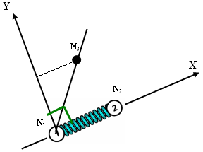
Figure 1. - The /SPRING card is also used to define /PROP/TYPE45 (KJOINT2) joints. For each joint type, node_ID1 and node_ID2 are used to define the joint itself. node_ID1 must be attached to one rigid body and node_ID2 to another rigid body. These nodes can be non-coincident, but for better behavior of the joints, it is strongly advised to use initially coincident nodes. Optional nodes node_ID3, node_ID4 are used for definition of local coordinate systems on two sides of joint. Initially the coordinate systems are coincident. Behavior of the joint is determined by relative motion/rotation of these local coordinate systems.
- For spherical and rigid joints only node_ID1 and node_ID2 are required. Local coordinate system of
the joint is initially defined with node_ID1, node_ID3 and node_ID4 or with the global coordinate system (if
node_ID3 and node_ID4 are node defined).
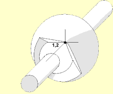
Figure 2. Spherical Joint - For revolute,
cylindrical, translational and planar joints, node_ID3 is used to define the first axis of the
joint coordinate system. If node_ID3 is not specified, the axis of the joints
is defined using the line between node_ID1 and node_ID2. In this case, the nodes should not be
coincident.
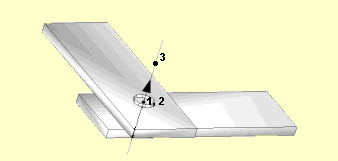
Figure 3. Revolute Joint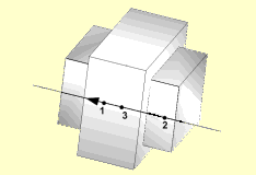
Figure 4. Translational Joint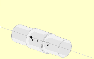
Figure 5. Cylindrical Joint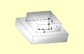
Figure 6. Planar Joint - For universal and free
joints, node_ID3 and node_ID4 are used to define the first and the
second axis of the joint coordinate system.
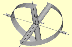
Figure 7. Universal Joint - When joint properties are non-isotropic (not the same stiffness, friction or damping for each non-blocked DOF), a full definition of local coordinate systems is required. In this case the first axis of the local coordinate system is defined by node_ID3, the second axis of the local coordinate system is defined by node_ID4, and the third axis is computed automatically.
- Both node_ID5 and node_ID6 are reserved for future use for new joints types.