/INTER/TYPE2
Block Format Keyword Defines a TYPE2 tied interface that connects a set of slave nodes to a master surface. It can be used to connect coarse and fine meshes, model spotwelds, rivets, and so on.
Format
| (1) | (2) | (3) | (4) | (5) | (6) | (7) | (8) | (9) | (10) |
|---|---|---|---|---|---|---|---|---|---|
| /INTER/TYPE2/inter_ID/unit_ID | |||||||||
| inter_title | |||||||||
| grnd_IDs | surf_IDm | Ignore | Spotflag | Level | Isearch | Idel2 | dsearch | ||
Read this input, if Spotflag = 20, 21, or 22:
| (1) | (2) | (3) | (4) | (5) | (6) | (7) | (8) | (9) | (10) |
|---|---|---|---|---|---|---|---|---|---|
| Rupt | Ifiltr | fct_IDsr | fct_IDsn | fct_IDst | Isym | Max_N_Dist | Max_T_Dist | ||
| Fscalestress | Fscalestr_rate | Fscaledist | Alpha | Area | |||||
Read this input, if Spotflag = 25, 27 or 28:
| (1) | (2) | (3) | (4) | (5) | (6) | (7) | (8) | (9) | (10) |
|---|---|---|---|---|---|---|---|---|---|
| Stfac | Visc | Istf | |||||||
| (1) | (2) | (3) | (4) | (5) | (6) | (7) | (8) | (9) | (10) |
|---|---|---|---|---|---|---|---|---|---|
| Ithe | Kthe | Iproj | |||||||
Definitions
| Field | Contents | SI Unit Example |
|---|---|---|
| inter_ID | Interface
identifier (Integer, maximum 10 digits) |
|
| unit_ID | Unit Identifier (Integer, maximum 10 digits) |
|
| inter_title | Interface
title (Character, maximum 100 characters) |
|
| grnd_IDs | Slave node group
identifier. (Integer) |
|
| surf_IDm | Master surface
identifier. (Integer) |
|
| Ignore | Flag to ignore slave nodes
if no master segment found.
|
|
| Spotflag | Spotweld formulation flag.
3
4
5
6
7
11
(Integer) |
|
| Level | Hierarchy level of the
interface. (Integer) |
|
| Isearch | Search formulation flag
for the closest master segment.
(Integer) |
|
| Idel2 | Node deletion flag. 9
10
16
(Integer) |
|
| dsearch | Distance for searching
closest master segment. Default value is the average size of the master segments. 13 (Real) |
|
| Rupt | Failure model (only
available with Spotflag
20, 21 or 22).
(Integer) |
|
| Ifiltr | Filter flag. 10
(Integer) |
|
| fct_IDsr | Stress factor vs stress
rate function identifier. 6
(Integer) |
|
| fct_IDsn | Max normal stress vs
normal relative displacement function identifier
(N_Dist). This function must be defined. 6 (Integer) |
|
| fct_IDst | Max tangential stress vs
tangential relative displacement function identifier
(T_Dist). This function must be defined.
6 (Integer) |
|
| Isym | Asymmetric rupture flag.
6
(Integer) |
|
| Max_N_Dist | Maximum normal relative
displacement. Default = 1e+20 (Real) |
|
| Max_T_Dist | Maximum tangential
relative displacement. Default = 1e+20 (Real) |
|
| Fscalestress | Stress scale factor. 6 Default = 1.00 (Real) |
|
| Fscalestr_rate | Stress rate scale factor.
6 Default = 1.00 (Real) |
|
| Fscaledist | Distance scale factor.
6 Default = 1.00 (Real) |
|
| Alpha | Stress filter alpha
value. Default = 1 (Real) |
|
| Area | Area of surface which used when the area computed from slave
node side is null or when slave node is connected only to 1D
element. Default = 0.0 (Real) |
|
| Stfac | Stiffness factor (used only with Spotflag
25, 27 or
28). Default = 1.0 (Real) |
|
| Visc | Critical damping coefficient on interface stiffness (used only
with Spotflag
=25, 27 or
28). Default = 0.05 (Real) |
|
| Istf | Interface stiffness
definition flag. 16 Only used with penalty
formulations (Spotflag=25,
27 or 28).
(Integer) |
|
| Ithe | (Optional) Heat transfer
flag.
(Integer) |
|
| Kthe | (Optional) Heat exchange
coefficient. Default = 0.0 |
|
| Iproj | (Optional) Slave node
projection flag. 18 (not available for Spotflag = 1,
28 and 30).
(Integer) |
Comments
- Interface TYPE2 is a kinematic condition; no other kinematic condition should be set on any node of the slave surface, except when Spotflag =25, 27 or 28.
- The dsearch is computed as (see Tied Interface (TYPE2) in the Radioss Theory Manual):
(1) with,- Being the number of master segments
- Tthe total length of all the master side segments
- Master nodes of an interface TYPE2 may be slave
nodes of another interface TYPE2 only if the hierarchy level of the first
interface is lower than the hierarchy level of the second interface. Hierarchy
levels are only available with Spotflag =2. It does not
work if Spotflag =0 or Spotflag =1.
A possible workaround is using Spotflag=2, which corresponds to the default formulation (Spotflag=0); except that it is not compatible with /DT/NODA/CST.
- Spotflag =2 is equivalent to formulation 0; except that it is not compatible with nodal time step /DT/NODA/CST.
- Spotflag =4 is recommended to connect SPH particles to a surface (refer to Smooth Particle Hydrodynamics (SPH)).
- Spotflag = 20,
21 or 22 can include falure and be used to
model a glue connection. It is not compatible with nodel time step
/DT/NODA/CST. The stress is computed for each slave node
according to the "equivalent" surface around the node.In this case, the force in slave node will be scaled by reduced force coefficient Fac_N (Fac_T), which is computed as:
(2) (3) The reduced force is compared to the max value:
if , then Fac_N =1, which means the force will not be reduced.
if , then , which means the force will be reduced.
Here the max value will be defined by the user with:(4) (5) (6) While, , and are functions of fct_IDsn, fct_IDst and fct_IDsr.
Once the rupture criterion (defined by Rupt) is reached, the contact will be deleted.
Here:- is the maximum normal stress value defined by fct_IDsn
- is the normal stress
- T_max is the maximum tangential stress value defined by fct_IDst
- is the tangential stress
- Fscalestress is the input constant stress factor
- fct_IDsr is the input variable coefficient
- fct_IDsn and fct_IDs are the input stress-displacement functions
- Isym permits to choose between symmetric or asymmetric rupture (traction/compression). The initial direction from master surface to the slave node defines the positive side (traction). If the distance is zero (slave node lies on the master surface), the rupture will be symmetric, even with Isym =1.
This failure option (Spotflag = 20, 21 or 22) can not be used in implicit.
- Spotflag =30: Slave
mass/inertia/stiffness distribution to the master node is based on the Kirschoff
model: bi-cubic form functions are used instead of linear (standard
formulation). It allows a softer contact behavior since the element shape
curvature is taken into account in the force/moment transmission.Warning: This formulation is not compatible with solid elements, as it requires rotational DOF.
- If flag Idel2 =2, then when a 4-node shell, a 3-node shell or a solid element is deleted, it is also removed from the master side of the interface (the kinematic condition is suppressed on relative slave nodes).
- The options Idel2 =1 and Idel2 =2 act if the master element is deleted using explicit deletion in Radioss Engine (using the keyword /DEL in Radioss Engine Input (/DEL/SHELL, /DEL/BRICK, ...)).
- If Ifiltr is set to 1, the
normal and tangential stresses are filtered with an alpha filter, as:
(7) (8) - Spotflag =25 (penalty
formulation) will keep the penalty formulation during the whole run. The slave
node (of this contact) could also be the slave node of another kinematic option,
like rigid body.
The penalty stiffness is constant, calculated by default as the mean nodal stiffness of master and slave side. The stiffness factor, Stfac, may be used to modify it, if needed. The penalty stiffness will be multiplied by Stfac.
A critical viscous damping coefficient (Visc) allows damping to be applied to the interface stiffness.
- If Ignore = 1, 2, or 3, the slave nodes without a master segment found during the Starter, are deleted from the interface.
- If Ignore ≠ 1000, dsearch is used.If Ignore = 2 or 3 and dsearch = 0, dsearch is computed, for each slave node as:
(9) (10) For shells:- thickness_slave_node = shell thickness of slave
- thickness_master_segment = shell thickness of master
For solids:- thickness_slave_node = 0
If Ignore = 2:- thickness_master_segment =
If Ignore = 3:- thickness_master_segment = 0
If Ignore = 2 or = 3:- Thickness is retained in the following order: first from /PART definition, from /SHELL or /SH3N definition, then from /PROP definition.
- The contact is compatible with 2D-plane and -axisymmetrical simulations only for Spotflag=0 and in case of connecting to solid elements with Spotflag=0, then moments are not transferred.
- If flag Idel2 =1, then when all 4-node shells, all 3-node shells and all solid elements belonging to a master segment are deleted, this segment is also removed from the master side of the interface (the kinematic condition is suppressed on relative slave nodes).
- Spotflag = 25,
27 or 28: Interface penalty stiffness is
computed from both master segment stiffness
Km and slave node
stiffness Ks, depending on Istf flag:
- Istf = 1:
- Istf = 2 (default):
- Istf = 3:
- Istf = 4:
- Istf = 5:
- If Ithe >1, the material
of the slave side and master need to be a thermal material, using finite element
formulation for heat transfer (/HEAT/MAT).
Thermal conduction is computed when the slave node falls into contact.
The heat exchange is computed from master to slave and from slave to master:(11) - By default,
Iproj
=1 is used to avoid having the wrong mass distribution when
the slave node is projected outside of the master element. The mass and inertia
are distributed on the closest edge based on the projection of the slave node on
this edge. Use Iproj
=2, to obtain the same results as Radioss version 14.0 or older.
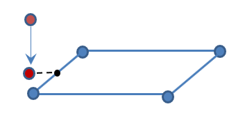
Figure 1. - When using the penalty formulation Spotflag=25, moments cannot be transmitted from the slave nodes to a master segment. Therefore, it is not recommended to use it for any connection where the slave nodes have rotational degrees of freedom. This would include: shell to shell, spring to shell, shell to solid where the shell is slave and solid is master. Due to this limitation and the lower robustness compared to kinematic formulations, it is recommended to use the mixed kinematic and penalty formulation, Spotflag =27 and 28.
- Spotflag =27 and
28 are a mixed kinematic and penalty formulation tied
contact. By default, the kinematic formulation is used. Any slave nodes with
incompatible kinematic conditions are automatically switched to the penalty
formulation. Incompatible kinematic conditions with rigid bodies, imposed
displacements, imposed velocities, imposed accelerations, other tied contact
slave nodes, or boundary conditions will cause the switch to penalty
formulation. A WARNING message is printed in the Starter output file when slave
nodes are switched to penalty formulation.
The penalty formulation stiffness is constant and calculated using Istf and Stfac. A critical viscous damping coefficient (Visc) allows damping to be applied to the interface stiffness. The penalty formulation can transfer moments from the slave nodes to the master segment.
- Unlike Spotflag =1, Spotflag =28 does not add any mass at time=0 when the master surface of the tied contact is a shell element. If the master surface is a solid element there could be some mass added. No mass is added when Spotflag =27 is used.