Use the Edit: Replace tool
to relocate and replace the positions of nodes.
The Edit tools work for tessellated
geometry. If the input is b-spline geometry, first convert to discrete geometry
using the Convert tool.
-
From the Geometry ribbon, FE Geometry tools, click .
Elements are colored according to how
well they adhere to the pre-set quality requirements defined in the criteria
file.
-
Select an element issue type from the guide bar.
- Quality
- Checks for quality as defined in quality criteria.
- Intersections
- Checks for intersecting elements.
- Face angles
- Checks for folded or sharp angle elements.
- Optional:
Find all elements at or below a certain quality level.
-
Click Find on the guide bar.
-
Increase or decrease the number of layers around patches of failed
elements by clicking
 or
or  on the guide bar.
-
Review the next or previous patch of failed elements by clicking
 or
or  on the guide bar.
-
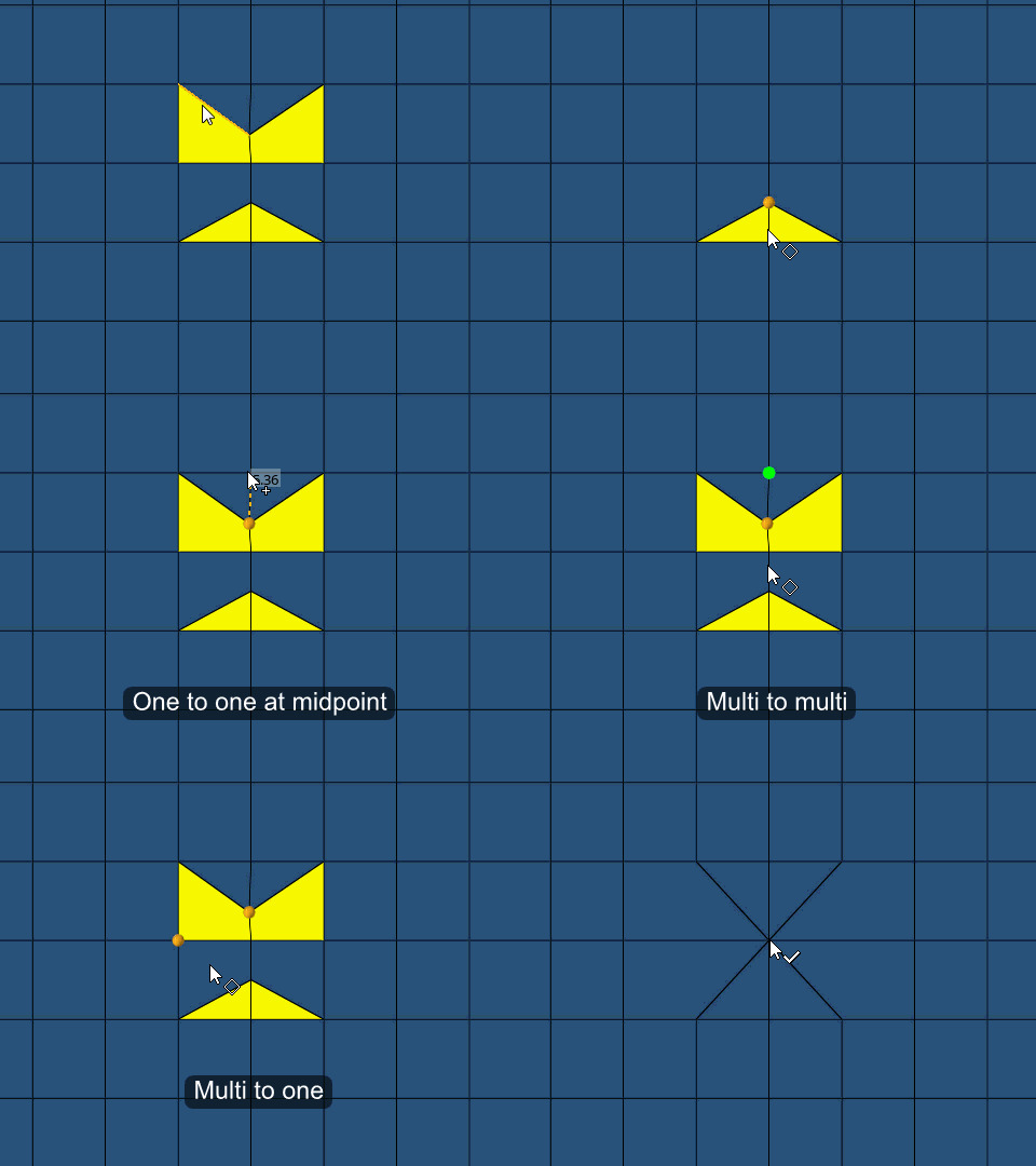
Select a replacement method from the guide bar then
select nodes/ element edges.
| Method |
Node Replacement Steps |
|---|
| One to One |
- Select a node to relocate and replace.
- Select a target node.
The second node replaces the
first.
Note: You can also perform one to one replacement by selecting an
element edge to collapse. Selecting an element edge automatically
performs midpoint replacement.
|
| Multi to One |
- Select multiple nodes.
- From the selected nodes, left-click on a single target
node.
All other nodes are relocated to and replaced by
this node.
|
| Multi to Multi |
- Select a node to relocate and replace.
- Select a target node.
- Repeat this process as many times as desired.
- Left-click on a target node or click
Replace on the guide bar to replace all nodes at once.
|


 or
or  on the
  or
or  on the