Connect Intersecting 2D Elements
Connect intersecting triangular and quadrilateral 2D elements.
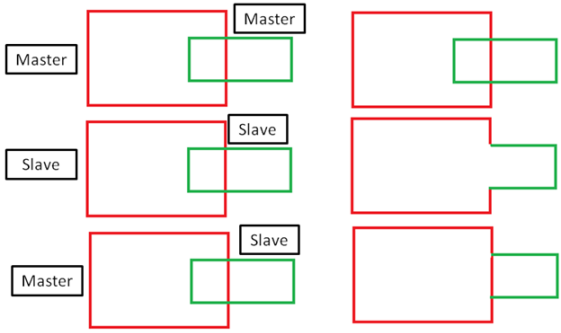
Several components\elements can be connected simultaneously. Components defined as master entities will be preserved. It is suggested that you ensure that 2D elements are properly intersecting.
-
From the Elements ribbon, click the arrow next to the
Edit tool set name and select Mesh
Boolean from the drop-down menu.
The Boolean Operation dialog opens.
-
Choose the type of boolean operation to perform.
- Choose Union.Figure 1. Union

- Choose Subtract.Figure 2. Subtract

- Choose Union.
-
Use the All entities to Boolean selector to select all components or elements
that will be involved in the boolean operation.
Entities defined that are not present in master entities to preserve are considered as slaves. If you define all entities for boolean as master entities to preserve, entities will intersect and connect components but will not remove any internal shells. The boolean operation will only remove internal shells if they are enclosed and if they belong to an entity not defined as master entities to preserve. If both of these conditions are not satisfied the internal shells will not be removed.
- Use the Master entities to preserve selector to select components that you do not want to remove internal shells for.
- If you have components with open shells but they are connected to other components and create closed shells together, select the Consider connected components as one shell checkbox to consider the closeness of the connected shells while deciding which internal shells will be removed.
- To create connection edges, select the Keep intersect edges checkbox.
-
To remesh elements near the intersection of inputs based on the defined
parameters, select the Local remesh at contacts
checkbox.
In a case of tria element input, tria elements of first order will be remeshed. In a case of quad elements input, remeshing will be done with mixed elements.
- In the Number of layers field, enter the number of additional layers next to the intersect edge to remesh.
- In the Feature angle field, enter the feature angle to use for the remeshed elements to be captured.
- In the Growth rate field, enter a growth rate to use for remeshing.
- Click Run.