RD-E: 2300 Brake
A brake system is simulated using a finite Lagrangian mesh element.
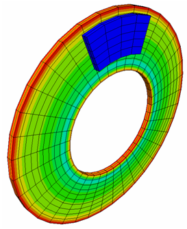
Figure 1.
Options and Keywords Used
- Brick elements and HEPH formulation
- Interface (/INTER/TYPE7) and friction
- Boundary conditions (/BCS)
For the disk's rigid bodies, all DOF, except the rotation around Y are fixed. For the pads' rigid bodies, all DOF; except translation around Y are fixed.
- Rigid body (/RBODY)
Two rigid bodies are created to put the disk into motion: the first (called RBODY1) contains all the nodes of the disk, except those in the disk's internal periphery, which are contained in the second rigid body (called RBODY2). Both rigid bodies are activated in the first step of computation; however, RBODY1 is deactivated in the D02 file.
Two other rigid bodies are created to model the pads' faces where concentrated loads are applied.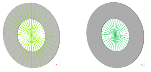
Figure 2. Rigid Bodies on the Disk (RBODY1 on the left and RBODY2 on the right)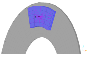
Figure 3. Rigid Body on a Pad - Initial velocities (/INIVEL)
An initial rotational velocity = 120 rad/s is applied to the disk's master nodes during the first computation phase.
- Concentrated load (/CLOAD)
Two concentrated opposite forces are applied to the rigid bodies' master nodes for the pads.
- Skew frame (Skews)
- Function (/FUNCT)
Input Files
- Lagrangian formulation
- <install_directory>/hwsolvers/demos/radioss/example/Lagrangian_formulation/BRAKE2*
Model Description
The purpose of this example is to highlight the capacity of Radioss to simulate frictional mechanisms. The braking system retained consists of a disk pinched in between two pads.
- Disk Description
- Radius
- 100 mm
- Width
- 50 mm
- Thickness
- 5 mm
- Mass
- 1 kg
- Inertia
- 0.57x10⁻² kg/m2 (about its free rotation axis)
- Pads Description
- Length
- 65 mm
- Width
- 28 mm
- Thickness
- 5 mm
A constant P = 300N pressure is applied on the back of each pad to push them against the disk. A Coulomb friction coefficient is assumed as being 0.15.
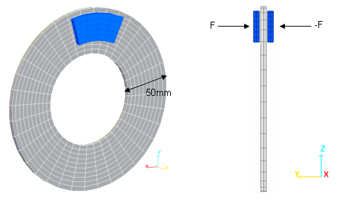
Figure 4. Geometry of the Problem
- Material Properties
- Initial density
- 7800 kg/m3
- Young's modulus
- 210000
- Poisson ratio
- 0.3
- Yield stress
- 206
- Hardening parameter
- 450
- Hardening exponent
- 0.5
- Maximum stress
- 340
- Material Properties
- Initial density
- 7300
- Young's modulus
- 160000
- Poisson ratio
- 0.3
Model Method
The two parts are modeled using a regular mesh having 720 BRICK elements for the disk and 80 such elements for the pads. The HEPH formulation is used to describe the BRICK elements.
Two steps are necessary to compute the model: First, an initial velocity 0.03 ms is applied to the disk. In the second step, pressure is applied to the pads to push them onto the disk.
Results
Angular Velocity of the Disk
The normal contact force between the pads and the disk is FN = 600N. Then the tangential friction force on the surface of the disk is obtained at FT = 0.15 x FN = 90N. The torque around the axis of the disk is T = r x FT = 7.1 Nm, with r = 0.0789 m, which corresponds to the orthogonal projection on a radial axis with regard to the distance between the center of the disk and the point of the pad where the load is applied. This leads to an angular deceleration of = 1246 rad/s2.
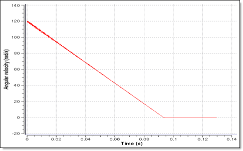
Figure 5. Angular Velocity of the Disk
Disk Rotation
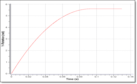
Figure 6. Total Rotation of the Disk
Reaction Forces
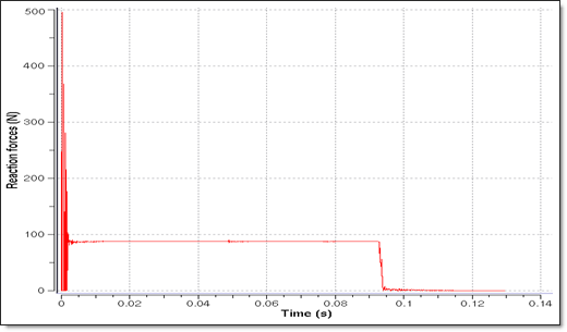
Figure 7. Reaction Forces
Energies
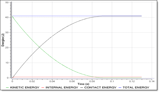
Figure 8. Energies
Contact Forces
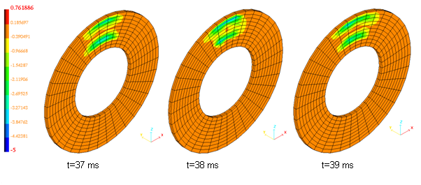
Figure 9. Variation of X-component of Tangential Contact Forces
Conclusion
The accuracy of the results obtained, using the simulation and corresponding to the analytical solution, proves that Radioss is able to simulate mechanisms, such as braking systems.