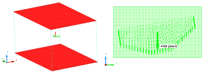
The fluid-structure interaction and the fluid flow are studied in cases of a fuel tank sloshing and overturning. A
bi-phase liquid-gas material with an ALE formulation is used to define the interaction between water and air in the
fuel tank.
The purpose of this example is to study the energy propagation and the momentum transfer through several bodies, initially
in contact with each other, subjected to multiple impact. The process of collision and the energetic behavior upon
impact are described using a 3-dimensional mode.
The impact and rebound between balls on a small billiard table is studied. This example deals with the problem of
defining interfaces and transmitting momentum between the balls.
After a quasi-static pre-loading using gravity, a dummy cyclist rides along a plane, then jumps down onto a lower
plane. Sensors are used to simulate the scenario in terms of time.
The purpose of this study is to demonstrate the use of quadratic interface contact using two gears in contact with
identical pitch diameter and straight teeth. Two different contact interfaces are compared.
The problem of a dummy positioning on the seat before a crash analysis is the quasi-static loading which can be resolved
by either Radioss explicit or Radioss implicit solvers.
The crashing of a box beam against a rigid wall is a typical and famous example of simulation in dynamic transient
problems. The purpose for this example is to study the mesh influence on simulation results when several kinds of
shell elements are used.
A square plane subjected to in-plane and out-of-plane static loading is a simple element test. It allows you to highlight
element formulation for elastic and elasto-plastic cases. The under-integrated quadrilateral shells are compared with
the fully-integrated BATOZ shells. The triangles are also studied.
The modeling of a camshaft, which takes the engine's rotary motion and translates it into linear motion for operating
the intake and exhaust valves, is studied.
The ditching of an object into a pool of water is studied using SPH and ALE approaches. The simulation results are
compared to the experimental data and to the analytical results.
A rubber ring resting on a flat rigid surface is pushed down by a circular roller to produce self-contact on the inside
surface of the ring. Then the roller is simultaneously rolled and translated so that crushed ring rolls along the
flat surface.
Polynomial EOS is used to model perfect gas. Pressure or energy can be absolute values or relative. Material LAW6
(/MAT/HYDRO) is used to build material cards for each of these cases.
Separate the whole model into master domain and sub-domain and solve each one with its own timestep. The new Multi-Domain
Single Input Format makes the sub-domain part definition with the /SUBDOMAIN keyword.
The Cylinder Expansion Test is an experimental test used to characterize the adiabatic expansion of detonation products.
It allows determining JWL EOS parameters.
The aim of this example is to introduce /INIVOL for initial volume fractions of different materials in multi-material ALE elements, /SURF/PLANE for infinite plane, and fluid structure interaction (FSI) with a Lagrange container.
A heat source moved on one plate. Heat exchanged between a heatsource and a plate through contact, also between a
plate and theatmosphere (water) through convective flux.
Impacts of rotating structures usually happen while the structure is rotating at a steady state. When the structure is
rotating at very high speeds, it is necessary to include the centrifugal force field acting on the structure to correctly
account for the initial stresses in the structure due to rotation.
The aim of this example is to introduce /INIVOL for initial volume fractions of different materials in multi-material ALE elements, /SURF/PLANE for infinite plane, and fluid structure interaction (FSI) with a Lagrange container.
RD-E: 5000 INIVOL and Fluid Structure Interaction (Drop Container)
The aim of this example is to introduce /INIVOL for initial volume
fractions of different materials in multi-material ALE elements,
/SURF/PLANE for infinite plane, and fluid structure interaction (FSI)
with a Lagrange container.
A hex mesh is created that fully encloses the structural container. The mesh size of
the hex mesh should be ½ the size of the structural mesh. Ideally the hex mesh should also
be ¼ of the structural mesh size in the direction of impact. To simplify this example, the
hex mesh in this model does not adhere to the ¼ mesh size guideline.
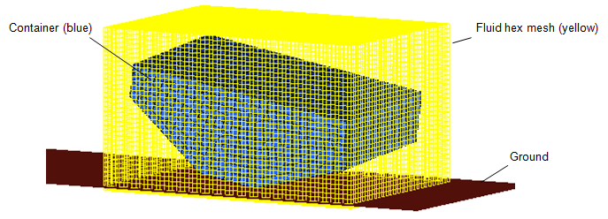
A container partially filled with water is simulated being dropped from a height of 1 meter. The
container is partially filled with water with the remainder filled with air.
Boundary Conditions
Each outer side of the hex mesh is constrained to prevent displacement in the
direction normal to the side. For example, the top and bottom of the hex mesh is
constrained in the z translation DOF (Figure 2). The same is done for the other four sides. The velocity at
impact of a drop from 1 meter would be 4429 mm/s. Since the simulation is started
right before impact, an initial velocity of 4429 mm/s is applied to the container
and the fluid hex mesh (Figure 2).
Units: mm, s, Mg, N, MPa
In one /MAT/LAW51 card, three different phases can be defined. The
two phases are: Air and Water
Air is defined with the following characteristics:
Reference density used in E.O.S (equation of state)
1.2e-12
Initial density of air
1.2e-12
Initial energy per unit volume
0.25
Hydrodynamic cavitation pressure
-1e-20
Hydrodynamic coefficient C41
0.4
Hydrodynamic coefficient C51
0.4
Water is defined with the following characteristics:
Initial density of water
1e-9
Hydrodynamic cavitation pressure
-1e-20
Hydrodynamic coefficient C03
0.10
Hydrodynamic coefficient C13
2250 (Liquid bulk modulus)
/ALE/MAT should also be defined for the
/LAW/MAT51 material, to indicate that is an ALE
model.
Coupled Euler_Lagrange (CEL) Interface
To define the contact between the fluid and the structure a visco-elastic penalty
formulation /INTER/TYPE18 interface is defined as:
Master is the Lagrange structure
Slave is the ALE fluid nodes
Gap is the Interface gap. The recommended value is 1.5 times fluid element size along
the normal direction to contact.(1)
Where,
The (highest) fluid density
The velocity.
For incompressible models (ditching, sloshing, etc.), use the
velocity of the event.
For compressible but not supersonic, use the speed of the sound
in the material.
Compressible and transonic (Mach 0.8 to 1.0), replace the term with
Where,
Speed of the sound in the material
speed of sound in air
Compressible and supersonic, use the velocity of the event
For an explosion, use the Chapman Jouguet velocity
The surface area of the Lagrangian elements
The interface gap, as defined above
For this example:(2)(3)
Simulation Iterations and Modeling
Fill Container with /INIVOL.
With
/INIVOL, the water line can be defined in this
part.
(1)
(2)
(3)
(4)
(5)
(6)
(7)
(8)
(9)
(10)
/INIVOL/part_ID/inivol_ID
inivol_title
surf_ID
ALE_PHASE
FILL_OPT
ICUMU
FILL_RATIO
surf_ID
ALE_PHASE
FILL_OPT
ICUMU
FILL_RATIO
etc
etc
etc
etc
etc
surf_IDn
ALE_PHASE
FILL_OPT
ICUMU
FILL_RATIO
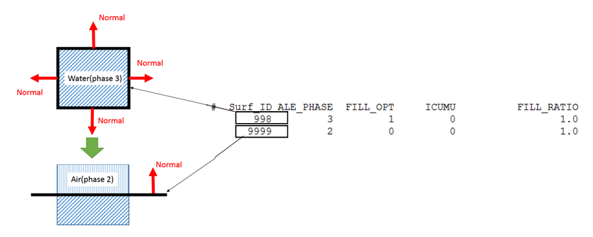
/INIVOL uses successive filling actions of the initial background
multi-material ALE mesh, to get the final configuration of the initial volume
fractions (three containers and three ALE phases). Initially the volume is filled by
the first material defined in the /MAT/LAW51 field. In this case,
the first material is air, so the entire hex mesh is first filled with air. Next, a
surface is defined from the container part
ID.
/SURF/PART/998
Vessel_Surf_Part
85
Since the surface normal of container part point outside, use
FILL_OPT = 1 to fill the water (phase 3) inside the container
(filling the side which against surface normal
direction).
Now, ALE mesh is filled with ALE material 1 (air) from /MAT/LAW51
on the outside of the container and material 3 (water) inside the container. Lastly,
define a surface plane, /SURF/PLANE to define the fill height.
The normal of this plane points upward, use FILL_OPT = 0 to fill
the air (phase 2) above the plane (filling the side along normal
direction).
To check the initial fill, the following animation options can be used in the Engine file.
/ANIM/ELEM/DENSITY
/ANIM/ELEM/VFRAC
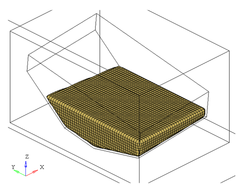
You can contour the model and use section cut to see inside, or use iso-surface, as
shown in Figure 4.
/ALE/MUSCL - Anti-diffusive Technique
/ALE/MUSCL allowing for a better localization
of the interface between fluids, and much less numerical diffusion. In this example,
use default for Beta.
/ALE/GRID/DONEA - ALE Grid Velocity
This activates the J. Donea Grid Formulation, where the velocity of a given grid node
depends on velocity and displacements of neighboring grid nodes.
Engine Control
It is recommended to use time step scale factor 0.5 for ALE in
/DT/BRICK in order to keep computation stable, and use
fac=1.0 in /UPWM/SUPG. This option
provides better velocity field in Cartesian grids when ALE material velocity is not
normal to brick faces.
Results
To see the movement of the water in the container, and iso-surface plot of results
type "density” can be done. If the simple averaging method is used in HyperView, the results will look smoother.
Also notice that water is starting to splash up the sides of the container at the end
of the simulation.